Turnable wall mount for display

a wall mount and turntable technology, applied in the field of display mounts, can solve the problems of not being able to achieve the necessary strength and stability of such a display mount, and not being able to provide a thin display mount, and achieve the effect of convenient implementation

Inactive Publication Date: 2013-05-16
SMS SMART MEDIA SOLUTIONS
View PDF8 Cites 6 Cited by
  • Summary
  • Abstract
  • Description
  • Claims
  • Application Information

AI Technical Summary

Benefits of technology

[0007]Another object of the present invention is to provide a thin display mount which allows the display to be angled at an arbitrary angle in relation to the surface on which the display mount is arranged which is less complicated than the display mounts according to the prior art.
[0008]A further object of the present invention is to provide a thin display mount which allows the display to be angled at an arbitrary angle in relation to the mounting surface on which the display mount is arranged in which the arm may be completely hidden behind the display in the position of the mount in which the display is closest to the mounting surface.
[0012]A display mount according to the invention enables the provision of a very thin display mount. The thickness of the display mount may be as thin as the thickness of the arm. Due to the slidability of the sled on the second bracket the attachment point of the arm in the sled may be moved in relation to the display. Thus, the arm may be considerably shorter compared to the arm on display mounts according to the prior art. A shorter arm may be made thinner than the arms according to the prior art. Furthermore, as the arm may be made considerably shorter than the arms according to the prior art the arm is easily hidden behind the display even when the arm is not foldable. A non-foldable arm is less complicated than a foldable arm.
[0016]The first device may be arranged to engage with the second device through snap action. Engagement through snap action is a well known principle and may easily be implemented by a man skilled in the art.
[0017]The first device may comprise a first profile and a second profile arranged in parallel to the first profile, wherein the arm is hinged between the first profile and the second profile and wherein the arm in the folded state of the display mount is arranged between the first profile and the second profile. Such an arrangement of the arm provides for a sturdy and stable display mount.

Problems solved by technology

It is not possible to provide a thin display mount by only decreasing the thickness of the mounts of the present design as it would not be possible to achieve the necessary strength and stability of such a display mount.

Method used


Image

  • Turnable wall mount for display
  • Turnable wall mount for display
  • Turnable wall mount for display

Examples


Embodiment Construction

[0024]In the following description of preferred embodiments of the invention similar elements or features in different figures will be denoted with the same reference numeral. It is to be noted that the drawings are not drawn to scale.

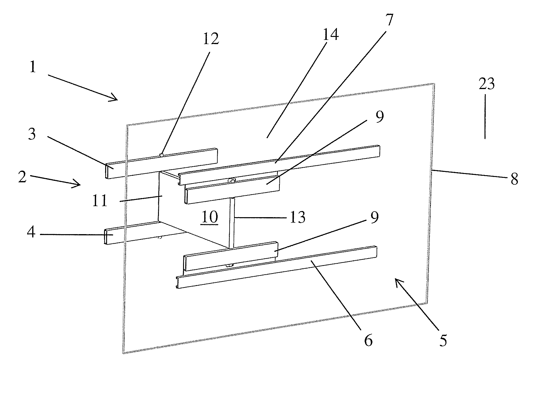
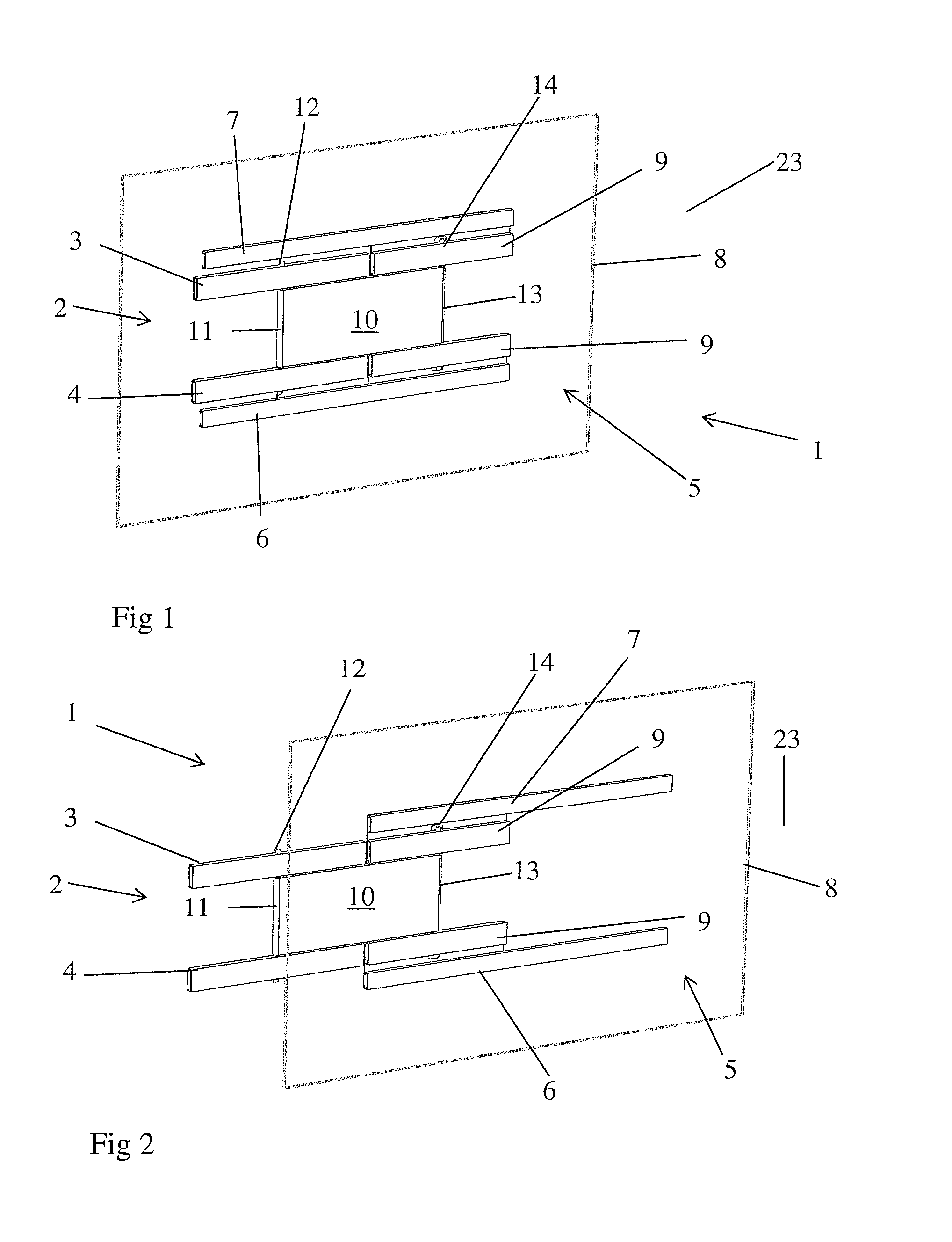
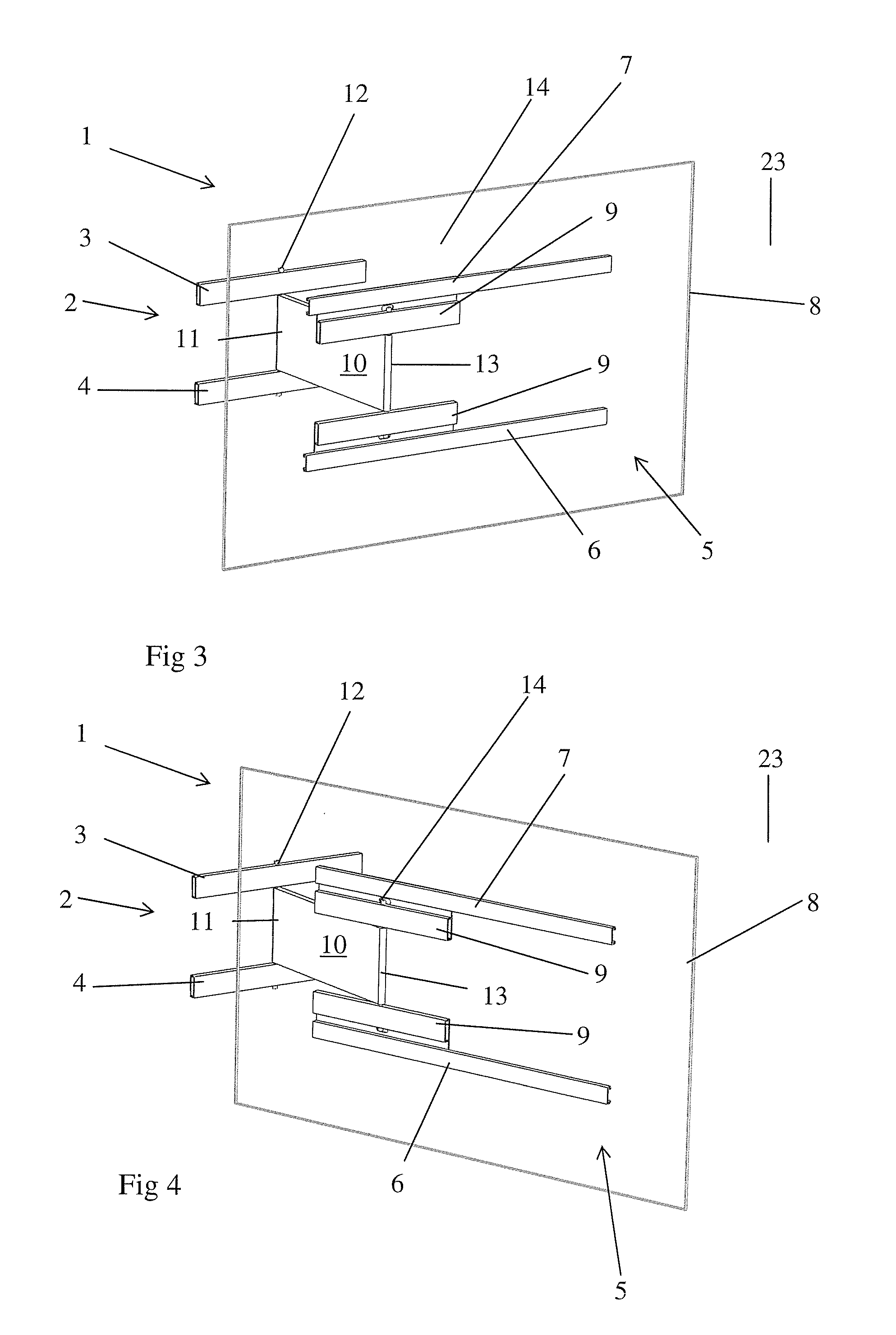
[0025]FIG. 1 is a perspective front view of a display mount 1 according to an embodiment of the present invention. The display mount 1 comprises a first device comprising a first bracket 2 in the form of two profiles 3, 4, to be fastened on a mounting surface 23. The display mount also comprises a second device comprising a second bracket 5 in the form of two parallel rails 6, 7, to be attached to the display 8 and sleds 9 which are slidably arranged on the rails 6, 7, of the second bracket. The display mount also comprises a rigid arm 10 which is arranged between the first bracket 2 and the second bracket 5. A first end 11 of the arm 10 is rotatably arranged on the first bracket 2 by means of a first axle 12 which is arranged through the two profiles ...


PUM


Abstract

A display mount (1) comprising a first device to be fastened on a mounting surface is described. The display mount comprises a second device to be fastened to a display (8) and an arm (10). A first end (11) of the arm (10) is rotatably arm ranged on the first device and a second end (13) of the arm (10) is rotatably arranged on the second device. The first device comprises a first bracket (5) and the second device comprises a second bracket (5) to be attached to the display (8) and sleds (9) which are slidably arranged on the second bracket (5). The second end (13) of the arm (10) is rotatably arranged on the sleds (9). In a folded state the display mount (1) has the display (8) close to and essentially parallel to the mounting surface.

Description

TECHNICAL FIELD[0001]The present invention relates to a display mount for mounting of a display on a vertical surface such as a wall. More specifically the present invention relates to a display mount which provides possibilities to angle the display in relation to the vertical surface.DESCRIPTION OF THE PRIOR ART[0002]Flat panel monitors and televisions are used extensively in commercial, residential and business environments. These flat panel displays enable an enhanced viewing experience and provide numerous advantages over the prior CRT monitors and TV's, of which the space savings is the most obvious advantage. Flat panel monitors may be mounted on a surface, such as a wall, a column, a post or a flat surface on a piece of furniture. A display mount is used to mount the display on the surface. It is advantageous if the display may be angled in relation to the surface on which the display is mounted. To this end the mount may be provided with a first device to be fastened on a m...

Claims


Application Information

Patent Timeline
Patent Type & Authority Applications(United States)
IPC IPC(8): F16M13/02
CPCF16M11/08F16M13/02F16M11/2085F16M11/2014F16M13/022
Inventor STRADSSON, PETTER
Owner SMS SMART MEDIA SOLUTIONS
Why Eureka
Try Eureka