
Active current sharing circuit

a current sharing and active technology, applied in the direction of power conversion systems, dc-dc conversion, dc source parallel operation, etc., can solve the problems of reducing the efficiency of the converter, and not providing any active current sharing, so as to achieve the effect of efficient supply of high power to a common load

Inactive Publication Date: 2005-05-17
ASTEC INT LTD
View PDF16 Cites 52 Cited by
  • Summary
  • Abstract
  • Description
  • Claims
  • Application Information

AI Technical Summary

Benefits of technology

[0009]The present invention solves the problems of prior art devices by providing, in a system comprising a plurality of paralleled converters, an active current sharing circuit that efficiently provides a load current sharing percentage for each converter connected in parallel that is approximately equal, for efficiently providing high power to a common load.
[0011]The present invention overcomes the drawbacks of known circuits and methods by providing a current sharing circuit that is lower in cost, has less complicated circuit wiring, has better space-effective utilization, provides an acceptable (high) current sharing level, and minimizes interconnections of the paralleled modules, while virtually eliminating the need for circuit tuning. The embodiments of the present invention are applicable for any power converters whose current can be sensed from its output inductors and which has a voltage reference coupled to its PWM controller error op-amps that is accessible.
[0012]Consequently, the circuit of the present invention has the advantage of enabling higher load current sharing from paralleled power converters while needing only lower cost components and fewer components as compared to prior art devices.

Problems solved by technology

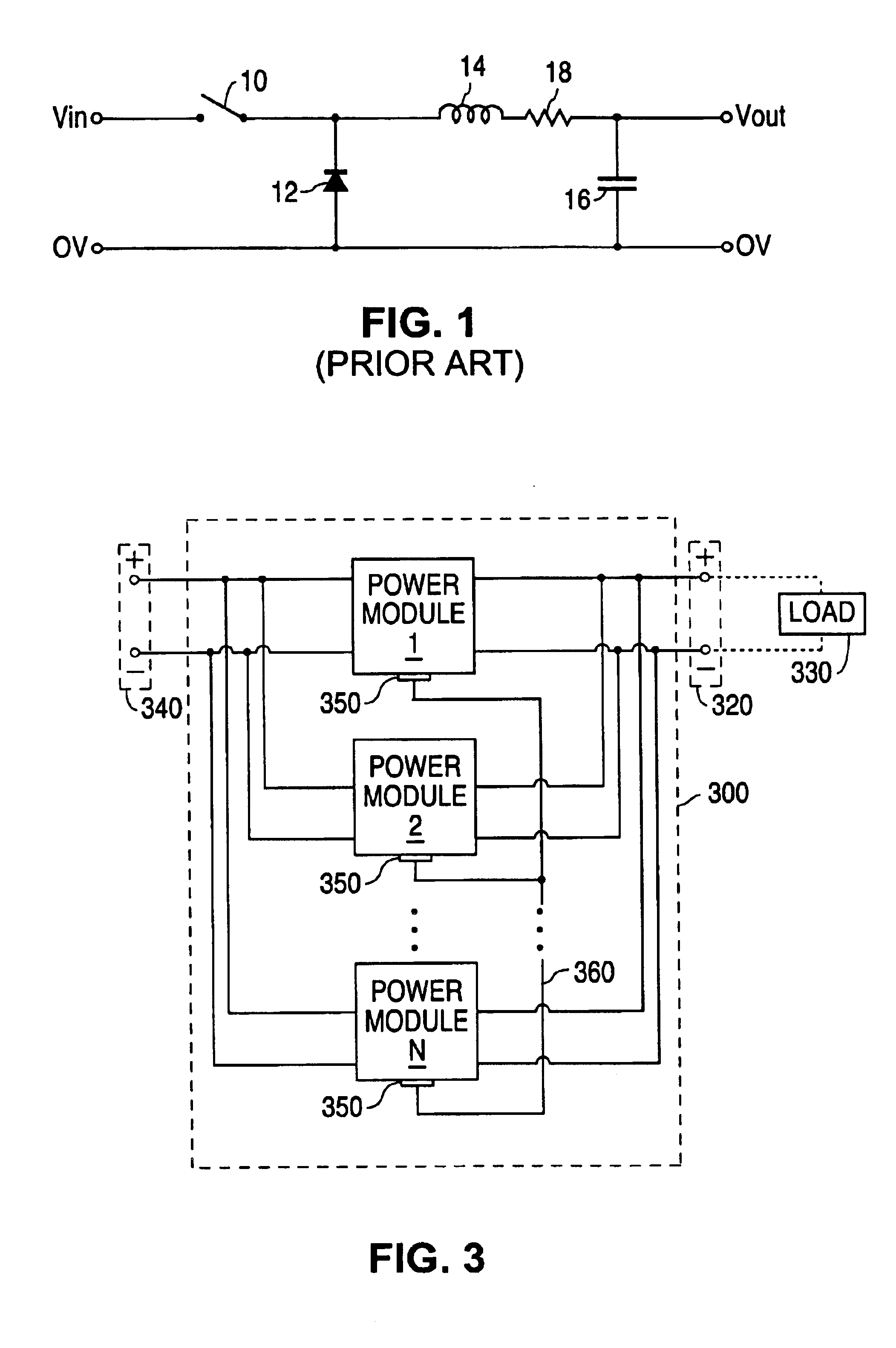
In practice, due to device tolerances, etc., such an assumption is not warranted.
A drawback of converter circuits that use a sense resistor is that significant power is lost in the sense resistors when the converters are providing high output currents, thereby reducing the efficiency of the converters.
This patent has the drawback of not providing any active current sharing to enable the current levels output by paralleled converters to be adjusted.

Method used


Image

  • Active current sharing circuit
  • Active current sharing circuit
  • Active current sharing circuit

Examples


Embodiment Construction

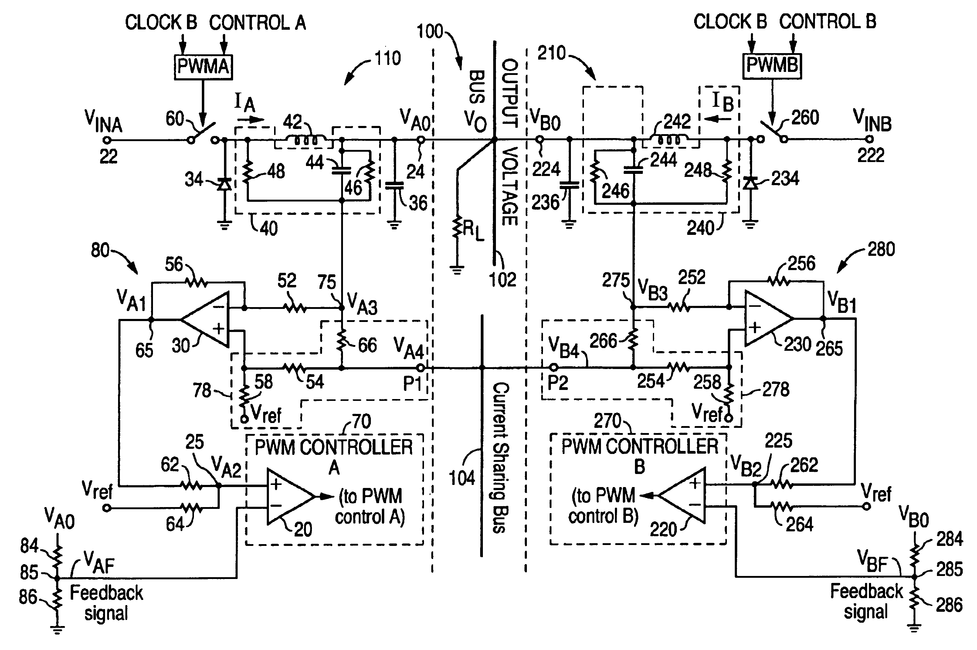
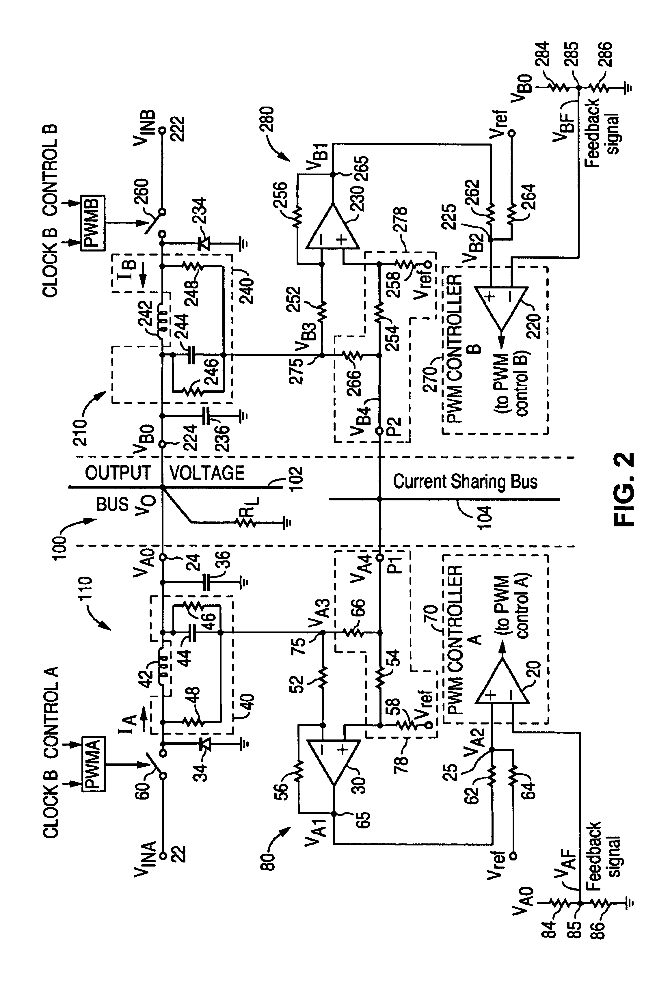
[0019]The present invention overcomes the drawbacks of known prior art circuits. A preferred embodiment of the active current sharing circuit for two paralleled DC Buck converters according to the present invention is shown in FIG. 2. The circuit 100 includes a power converter module 110 and a power converter module 210 connected in parallel. Converter modules 110 and 210 are preferably identical buck topology converters, shown as mirror images of each other in FIG. 2, having identical circuit components. As a result, the circuits and principles operating in one module also apply to the other module. Therefore, although some aspects of the converter module operation will be described solely with respect to converter module 110, the description applies to the other converter module 210. The corresponding elements in converter module 210 may also be given in parentheses herein for reference. For a preferred embodiment of FIG. 2, converter module 110 (210) has an input terminal 22 (222...


PUM


Abstract

An active current sharing circuit that provides a plurality of paralleled DC-DC converters each having a lossless inductor-based current sensing circuit for sensing the average current of the associated DC-DC converter through its output inductor, and a means for adjusting the voltage reference coupled to each of the DC-DC converter's PWM controllers through a one pin interconnection between the converters. The circuit provides a high percentage current sharing level at lower cost, with reduced circuit wiring complexity, and fewer components. In an alternate embodiment, the inductor-based current sensing is replaced with a resistor-based current sensing, such that comparable current sharing levels are achieved albeit with higher loss.

Description

CROSS REFERENCE TO RELATED APPLICATIONS[0001]This application is a continuation-in-part of application Ser. No. 10 / 377,864, entitled “Active Current Sharing Circuit”, filed Feb. 28, 2003 now abandoned.FIELD OF INVENTION[0002]The present invention relates to power converters, and more particularly, to a circuit that efficiently provides active current sharing for paralleled power converters.BACKGROUND OF THE INVENTION[0003]Many applications require that a higher level of current and power to be delivered to a load. At the same time, modem electronic devices require small, low cost, high density power converters. The paralleling of power converters provides a way for two or more individual, small, high density power converter modules to be coupled in parallel so as to supply the required power for high current loads and to provide redundancy. It is desirable that the individual converters in the parallel configuration share the load current equally in a stable, regulated manner. Furth...

Claims


Application Information

Patent Timeline
Patent Type & Authority Patents(United States)
IPC IPC(8): H02M3/158H02M3/04H02J1/10
CPCH02M3/1584H02J1/102
Inventor HUANG, HONGYOUNG, CHRIS M.
Owner ASTEC INT LTD
Learn More