
X-ray backscatter device for wellbore casing and pipeline inspection

a technology of x-ray backscatter and wellbore casing, which is applied in the direction of measurement devices, nuclear radiation detection, instruments, etc., can solve the problems of microbial induced corrosion, complicated material defect assessment and inspection process in wellbore casing and pipeline, and serious injury or even death, so as to achieve less time-consuming, less complicated, and less expensive

Active Publication Date: 2012-03-20
GAS TECH INST
View PDF11 Cites 51 Cited by
  • Summary
  • Abstract
  • Description
  • Claims
  • Application Information

AI Technical Summary

Benefits of technology

[0008]It is one object of this invention to provide an apparatus for in situ wellbore casing and pipeline inspection which is less complicated, less time-consuming, and less expensive than conventional devices.
[0009]It is one object of this invention to provide an apparatus for in situ wellbore casing and pipeline inspection which is able to operate in the extreme conditions, e.g. high pressures and temperatures, inside wellbores and pipelines.

Problems solved by technology

Scaling, corrosion, precipitates, and pipe and casing defects are all issues storage and pipeline operators face on a continual basis in managing the integrity of their production well and pipeline assets.
These defects often lead to diminished deliverability, on the order of 5 to 20%, in production wells, casing integrity issues requiring costly remediation, pipeline integrity issues requiring repair or replacement, and potentially catastrophic failures which may result in serious injury or even fatalities.
Conventional mineral scale formation, microbial induced corrosion, and material defect assessment and inspection processes in wellbores and pipelines are complicated, time-consuming, and very costly due to the range of operating conditions and existing inspection technologies.

Method used


Image

  • X-ray backscatter device for wellbore casing and pipeline inspection
  • X-ray backscatter device for wellbore casing and pipeline inspection
  • X-ray backscatter device for wellbore casing and pipeline inspection

Examples


Embodiment Construction

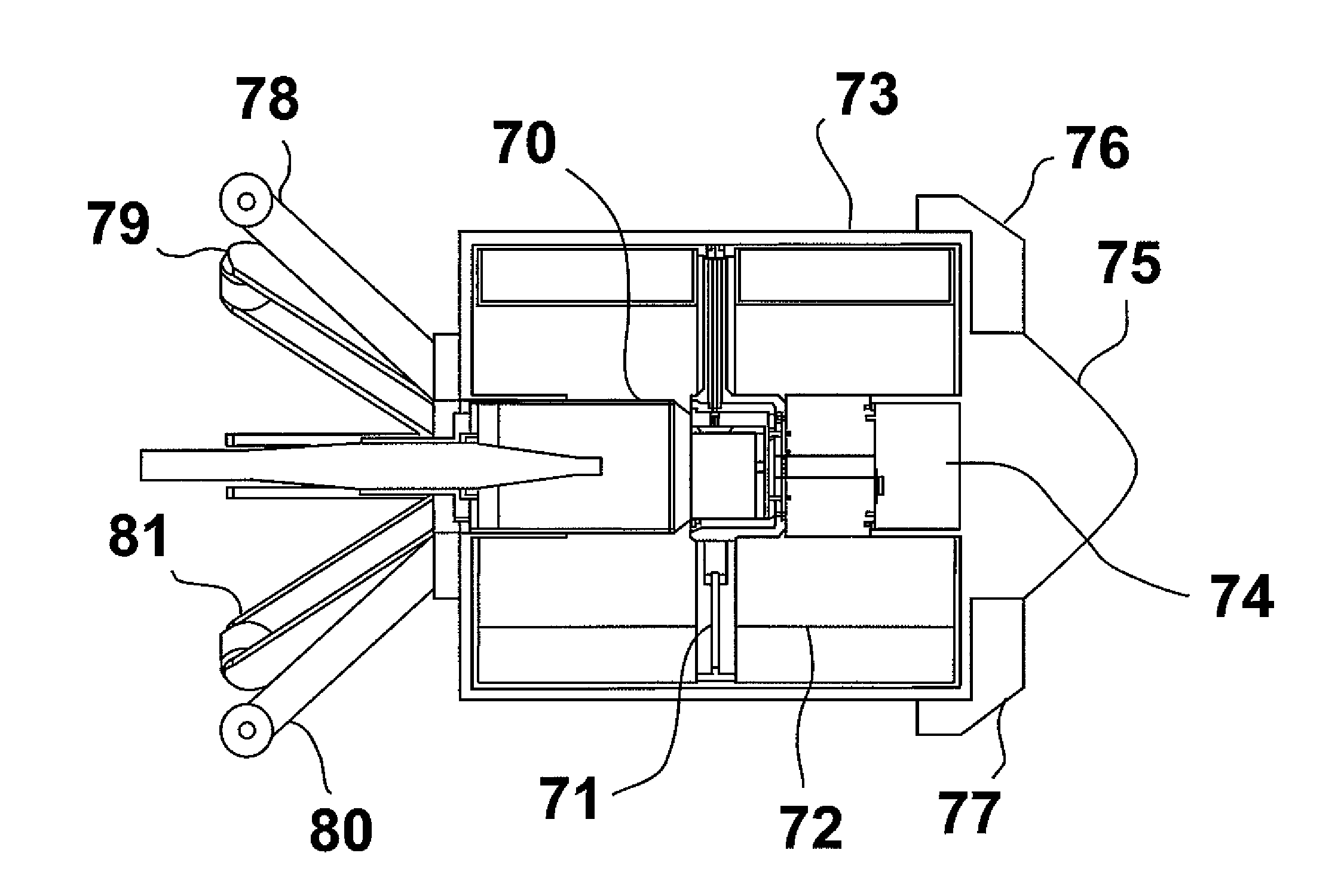
[0017]As previously indicated, Compton backscatter imaging is a single-sided imaging technique in which the radiation source and the detection / imaging device are located on the same side of the target object. As result, it is a valuable non-destructive inspection tool because of its single-sided nature, penetrating abilities of radiation, and unique interaction properties of radiation with matter. Changes in the backscatter photon field intensity (resulting in contrast changes in images) are caused by differences in the absorption and scattering cross-sections along the path of the scattered photons. Since the inception of Compton backscatter imaging, a diverse set of imaging techniques have evolved using both collimated and un-collimated detectors, coded apertures, and hard x-ray optics. Pencil beam backscatter imaging uses a highly collimated pencil beam of radiation to interrogate targets. The pencil beams may vary in diameter size from microns to centimeters, but usually consist...


PUM


Abstract

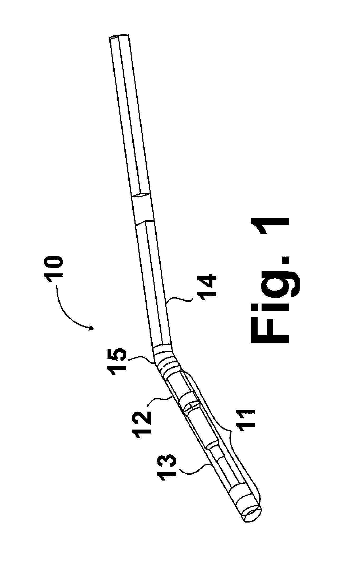
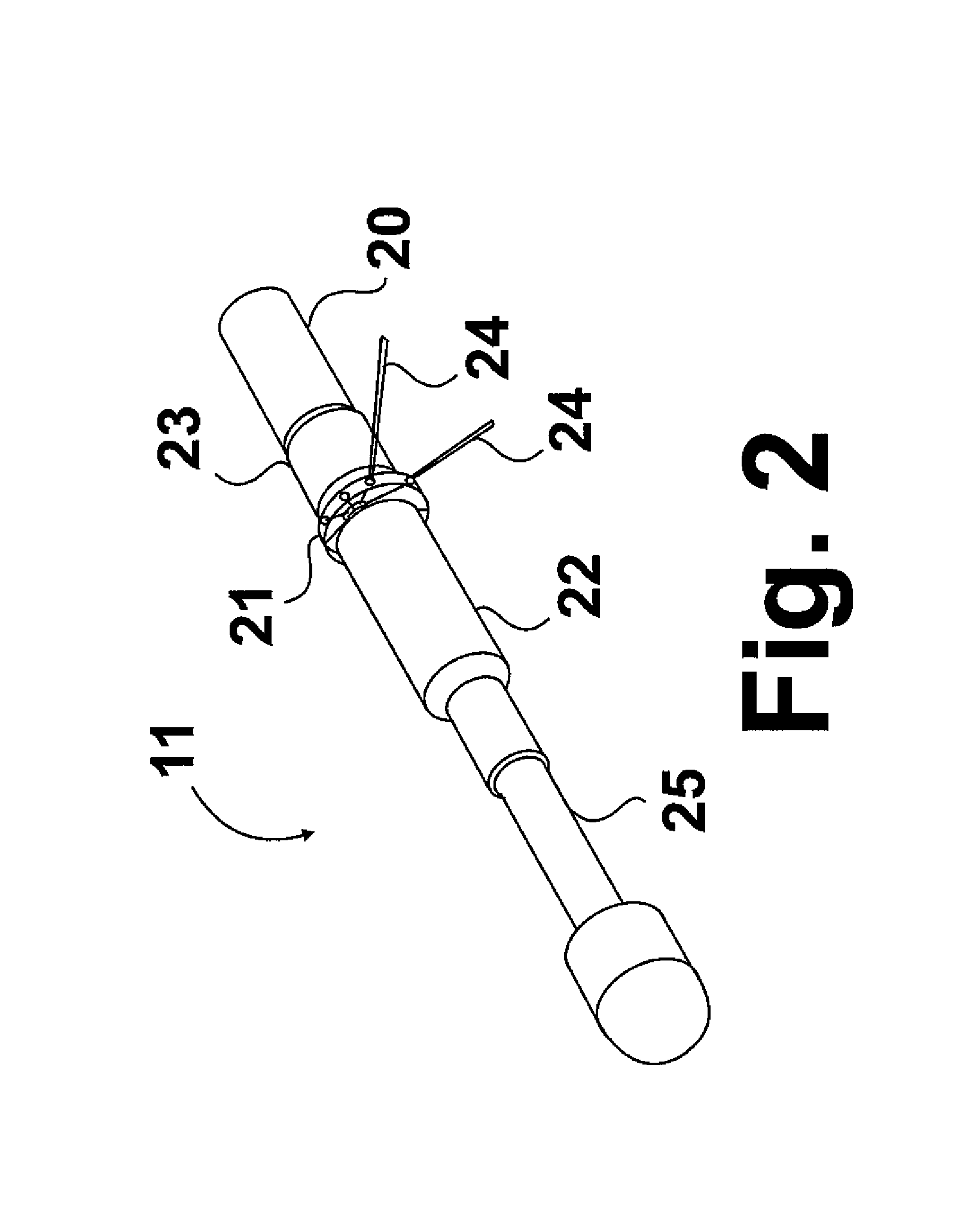
An apparatus for inspection in situ of a wellbore casing and a pipeline from inside the wellbore or pipeline. The apparatus includes a penetrating radiation source such as x-rays, a rotatable beam collimator adapted to collimate the penetrating radiation source and produce at least one pencil radiation beam rotatable about the radiation source, an arcuate radiation detector suitable for detecting radiation scattered off a target, and a housing containing the radiation source, the rotatable beam collimator, and the radiation detector. The housing is provided with at least one exit point for exiting of the at least one pencil radiation beam from the housing.

Description

BACKGROUND OF THE INVENTION[0001]1. Field of the Invention[0002]This invention relates to radiation backscatter imaging devices. In one aspect, this invention relates to x-ray backscatter imaging devices. In one aspect, this invention relates to in situ inspection of wellbore casings and pipelines. In one aspect, this invention relates to the use of radiation backscatter imaging devices for in situ inspection of wellbore casings and pipelines.[0003]2. Description of Related Art[0004]Scaling, corrosion, precipitates, and pipe and casing defects are all issues storage and pipeline operators face on a continual basis in managing the integrity of their production well and pipeline assets. These defects often lead to diminished deliverability, on the order of 5 to 20%, in production wells, casing integrity issues requiring costly remediation, pipeline integrity issues requiring repair or replacement, and potentially catastrophic failures which may result in serious injury or even fatalit...

Claims


Application Information

Patent Timeline
Patent Type & Authority Patents(United States)
IPC IPC(8): G01V5/08
CPCG01V5/08
Inventor SHEDLOCK, DANIELHAMMERSCHMIDT, ANDREW
Owner GAS TECH INST
Learn More