Liquid-Cooled Resistor Device

a resistor and liquid-cooled technology, applied in the direction of resistor details, resistor enclosure/embedding, cooling/ventilation/heating modification, etc., can solve the problems of limiting the efficiency and efficacy of heat transfer, bulky devices, and reducing the overall rate of heat dissipation of resistors, so as to improve heat transfer efficiency and efficacy, improve heat transfer efficiency, and improve heat transfer efficiency

Active Publication Date: 2013-05-16
CRESSALL RESISTORS
View PDF5 Cites 5 Cited by
  • Summary
  • Abstract
  • Description
  • Claims
  • Application Information

AI Technical Summary

Benefits of technology

[0008]Within the scope of this technical task, an advantage of the present invention is that of providing a liquid-cooled resistor device having improved efficiency and efficacy of heat dissipation from the resistor.
[0009]Another advantage is that of providing a liquid-cooled resistor device that is compact and lightweight.
[0010]A last but not least advantage of the invention is that of providing a liquid-cooled resistor device that is safe and economical.
[0011]These and other technical tasks, as well as these and other advantages, are achieved according to various embodiments of liquid-cooled resistor device according to present invention.
[0012]In one embodiment, a liquid-cooled resistor device includes a block that includes a liquid inlet, a liquid outlet and a cavity. The cavity can have a liquid flow path between the liquid inlet and the liquid outlet, and can further have an open side. A thermally conductive, electrically insulating flat layer is also included. The flat layer can be configured along a plane, with the flat layer covering the open side of the cavity. Also included is a resistor, also configured in a plane, where the plane of the resistor can be positioned parallel to the plane of the flat layer. A electrically insulating blocking plate, fastenable to the block, can be included, and can face the resistor to hold the resistor against the flat layer. Lastly, an elastic pressing device can exist between the block and the flat layer, the elastic pressing device forcing the flat layer against the resistor.
[0013]The use of a elastic pressing device to force the thermally conductive, electrically insulating flat layer against the resistor ensures improved heat transfer between the resistor and the flat layer. Moreover, the closure of the cavity of the block by the flat layer and the placement of the elastic pressing device in the cavity improves the heat transfer from the layer to the liquid. The overall heat transfer efficiency and efficacy improvement allows the device of the invention to be smaller and lighter than those of the noted prior art.

Problems solved by technology

One of the drawbacks of the devices of the prior art is that the thermal contact resistance at the resistor-block or resistor-insulation layer interface limits the efficiency and efficacy of the heat transfer.
Moreover, the low heat capacity of the block relative to the cooling liquid limits the overall rate of heat dissipation from the resistor.
Further, for use of the devices for braking inverter-driven electric motors, relatively large resistors and liquid-cooled blocks are required in order to manage the high energy dissipation requirements involved, which can in practice render the devices bulky and heavy.

Method used


Image

  • Liquid-Cooled Resistor Device
  • Liquid-Cooled Resistor Device

Examples


Embodiment Construction

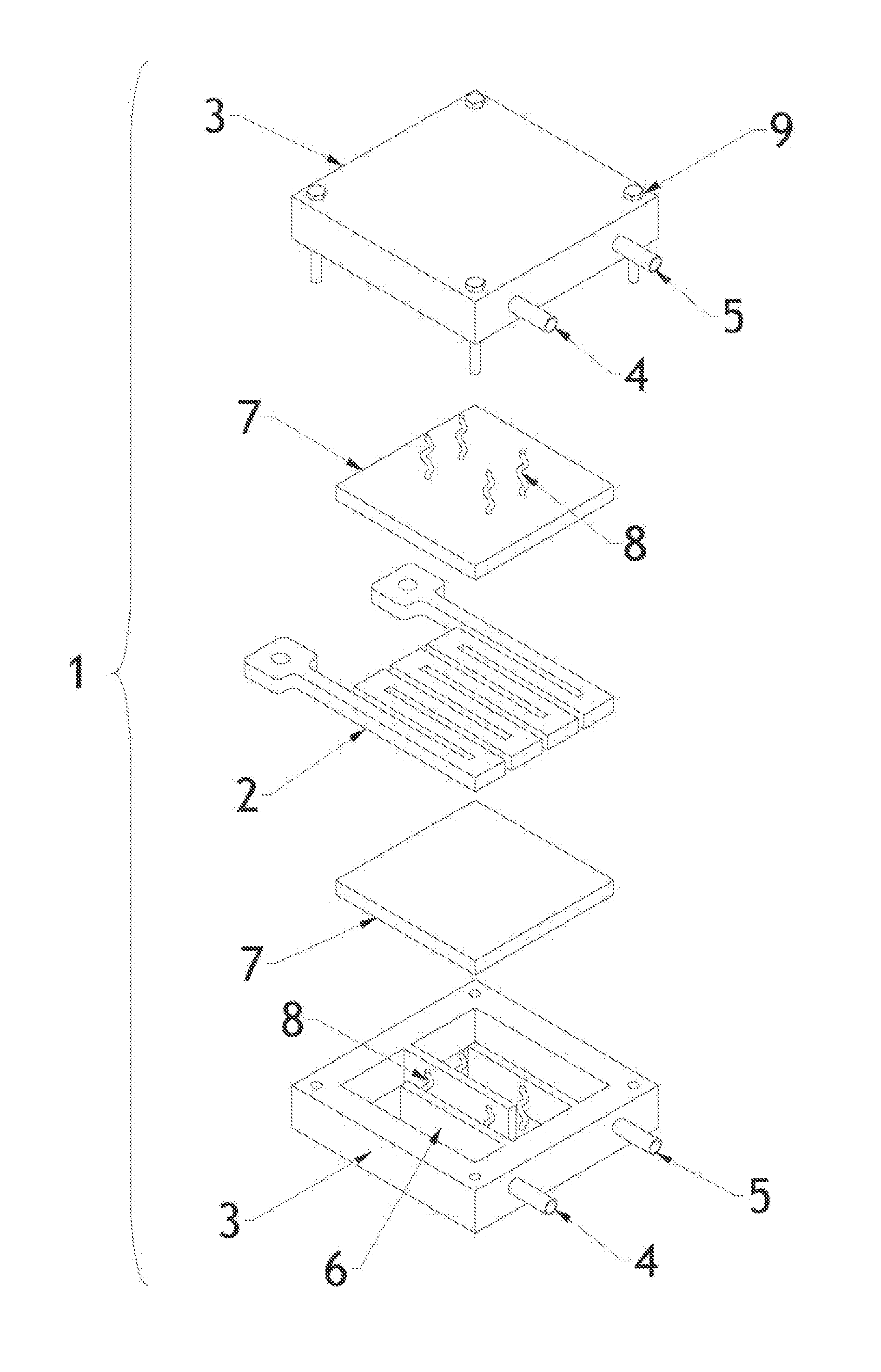
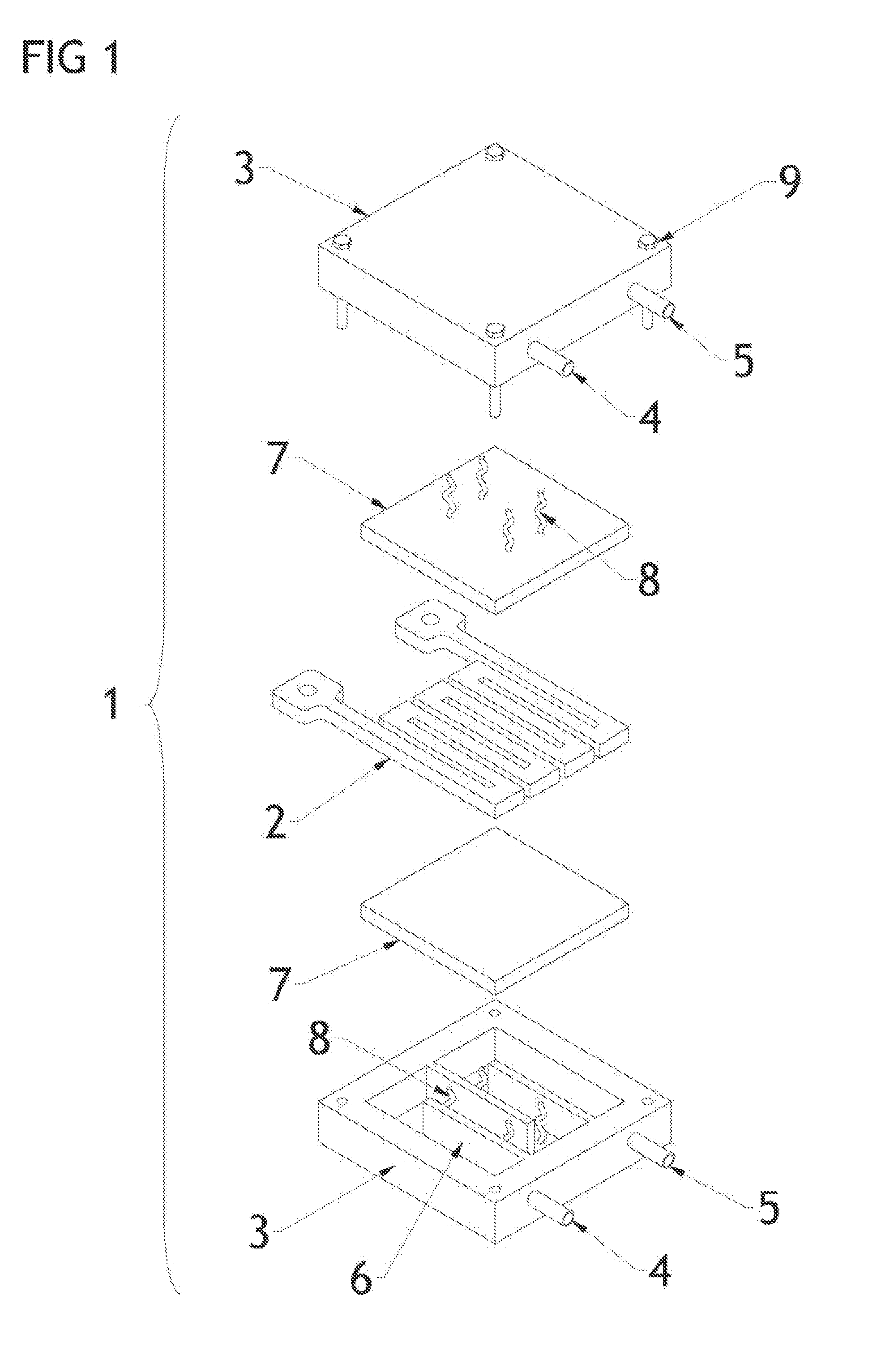
[0019]With reference to FIG. 1, the liquid-cooled resistor device (generally indicated by 1), comprises a resistor (2), preferably in the form of a flat grid of electrically resistive material. The electrical connection of said resistor (2) to a power circuit is preferably by terminals which are part of or connected to the resistor (2).

[0020]The resistor (2) rests on a thermally conductive, electrically insulating flat layer (7), disposed such that their main planes are parallel to one another. The flat layer (7) is preferably made of aluminium nitride ceramic and comprises a rigid sheet.

[0021]At least one block (3) is provided, preferably made of an electrically and thermally insulating material, in particular preferably moulded thermoset plastic. It is provided with a liquid inlet (4) and a liquid outlet (5), preferably disposed parallelly and as a function of the width of said block. The block further has a cavity provided with a liquid flow path (6) between the inlet (4) and the...


PUM


Abstract

A liquid-cooled resistor device including a block having a liquid inlet, a liquid outlet, and a cavity. The cavity is provided with a liquid flow path between the liquid inlet and the liquid outlet. The cavity can have an open side which is closed by a thermally conductive, electrically insulating flat layer. The flat layer can further support a flat resistor, the main plane of each being in parallel. The device can further include an electrically insulating blocking plate, fastenable to the block. The blocking plate can face the resistor to block the resistor on the flat layer. The device can also include a elastic pressing device positioned and configured to force the flat layer against the resistor.

Description

RELATED APPLICATIONS[0001]This application claims benefit of priority of European Patent Application No. 11009025.5, filed Nov. 14, 2011, in the name of Cressal Resistors Ltd.; which application is incorporated herein by reference.FIELD OF THE INVENTION[0002]The present invention relates to resistor devices; and more particularly to liquid-cooled resistor devices.BACKGROUND OF THE INVENTION[0003]Liquid-cooled resistor devices known from the prior art can be employed in a wide variety of applications, including regenerative braking of devices using an inverter-driven electric motor which can also function as a generator.[0004]DE 3933956 discloses a liquid-cooled resistor device for use in electric vehicles, with a flat resistor mounted between two liquid-cooled, electrically insulated blocks. The resistor is kept in place simply by rigid connection between the two blocks. GB2478547 discloses a liquid-cooled brake resistor device for use in electric vehicles, with a flat resistor is d...

Claims


Application Information

Patent Timeline
Patent Type & Authority Applications(United States)
IPC IPC(8): H01C1/082
CPCH01C1/02H01C1/082H01C3/12H05K7/20
Inventor NAZZARO, GIUSEPPE
Owner CRESSALL RESISTORS
Why Eureka
Try Eureka