Flight Control System Mode And Method Providing Aircraft Speed Control Through The Usage Of Momentary On-Off Control

Active Publication Date: 2013-05-30
EMBRAER SA
View PDF13 Cites 24 Cited by
  • Summary
  • Abstract
  • Description
  • Claims
  • Application Information

AI Technical Summary

Benefits of technology

[0004]The control interface between a pilot and the air control surfaces of an aircraft has received much attention over the history of aviation. The earliest control interfaces were very simple but required a great deal of pilot skill to operate. Modern “fly by wire” interfaces make use of a host of electronics to assist the pilo

Problems solved by technology

The earliest control interfaces were very simple but required a great deal of pilot skill to operate.
More specifically, longitudinal control laws often do not provide suitable landing flare characteristics, and in particular speed stability during landing.
However, this sort of solution has occasionally presented in-service events such as early flare activation during the approach due to erroneous height indication.
Radio altimeter information can be corrupted by external and internal causes, such as water flow dirt or ice

Method used


Image

  • Flight Control System Mode And Method Providing Aircraft Speed Control Through The Usage Of Momentary On-Off Control
  • Flight Control System Mode And Method Providing Aircraft Speed Control Through The Usage Of Momentary On-Off Control
  • Flight Control System Mode And Method Providing Aircraft Speed Control Through The Usage Of Momentary On-Off Control

Examples


Embodiment Construction

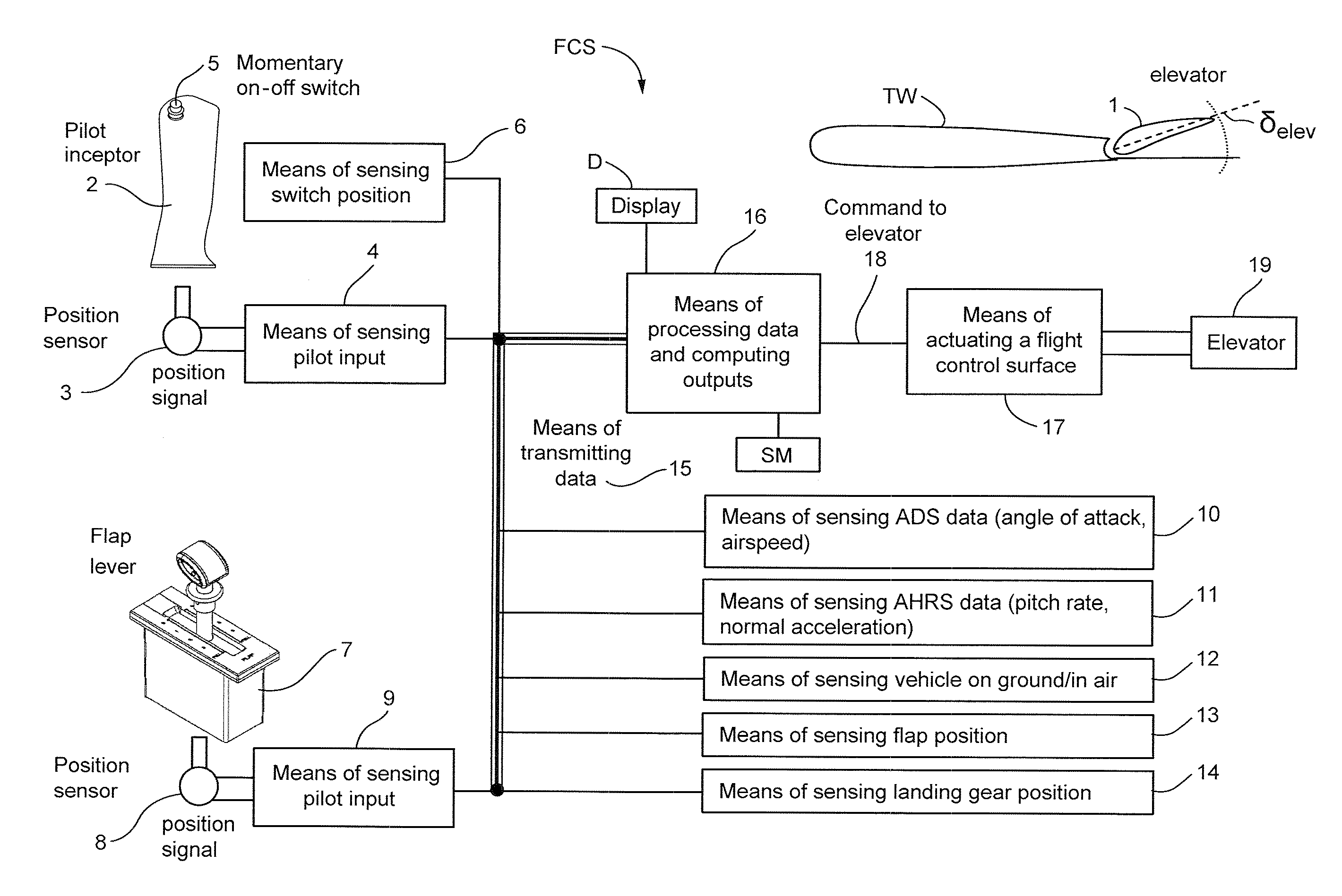
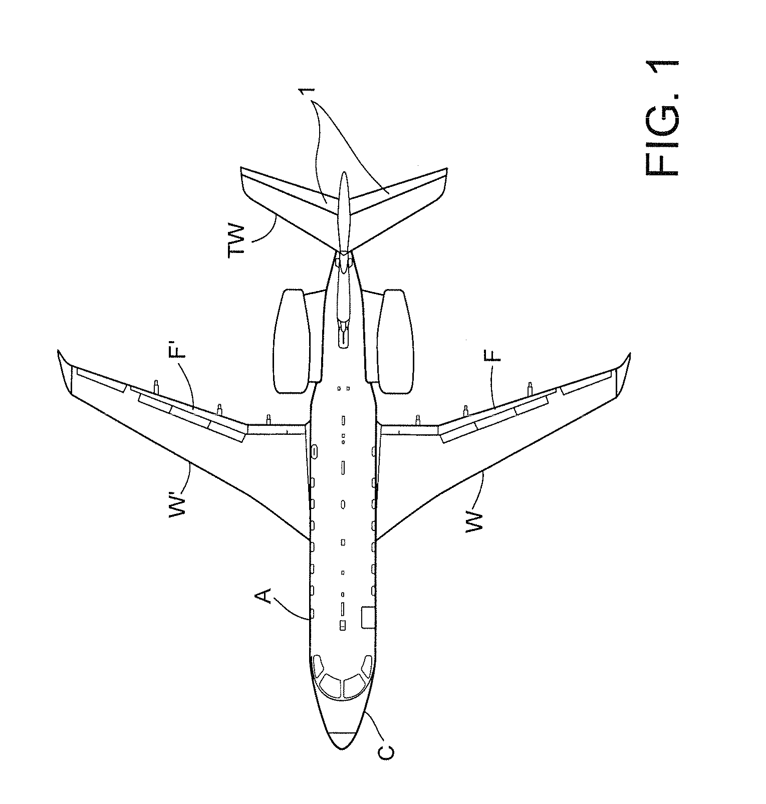
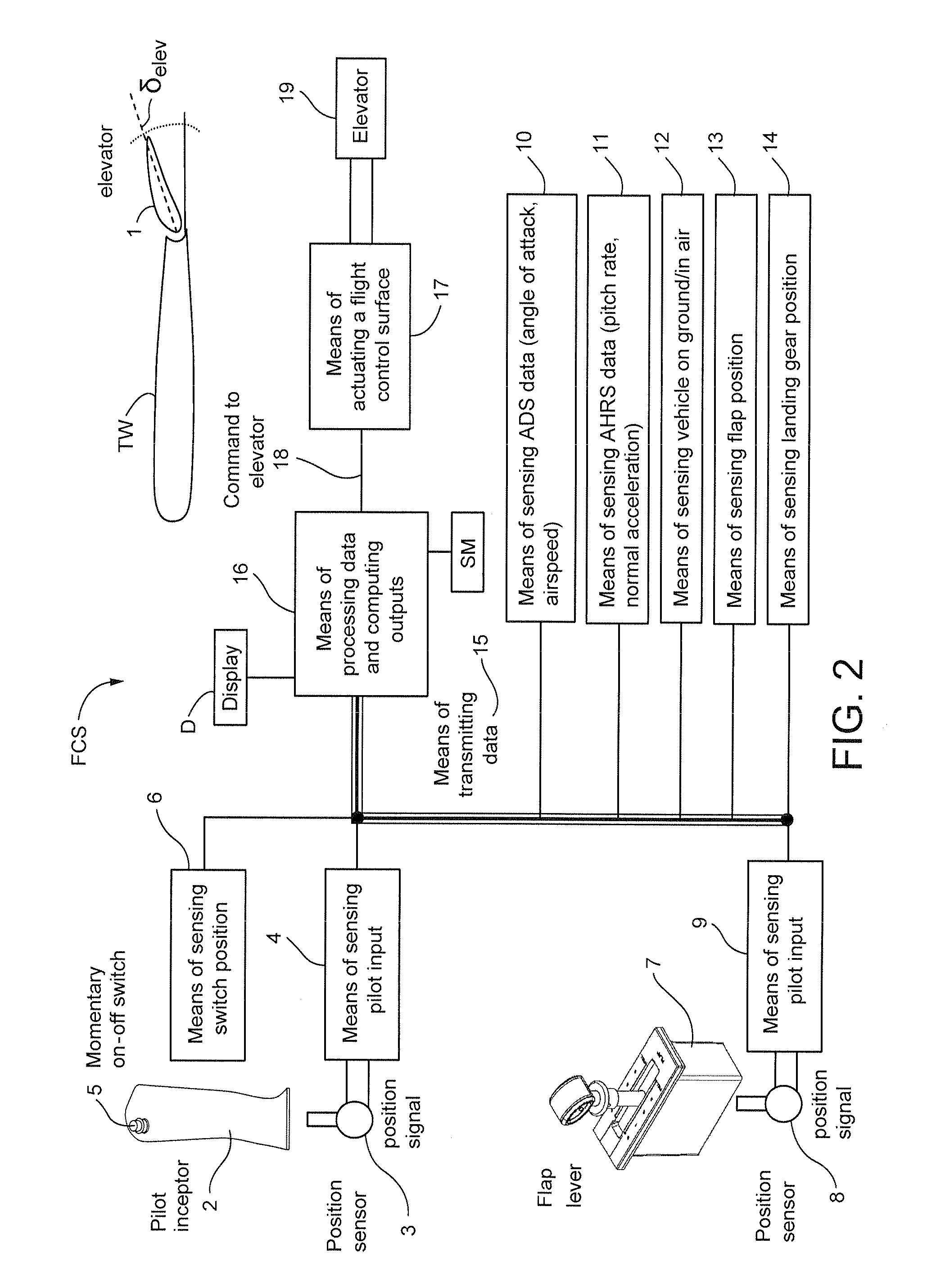
[0032]FIG. 1 shows an example: a twin turbo-fan engines civilian transporter aircraft A. Two elevators (1) are installed in the horizontal tail wing TW for pitch control, and two flaps F are installed in the main wings W for controlling lift and to slow the aircraft during landing. The tail elevators 1 control the pitch of the aircraft A during takeoff, flight and landing. The pilot in the cockpit C interacts with the aircraft A to control the control surfaces including flaps F and elevators 1. A fly-by-wire electronic flight control system accepts pilot input (e.g., through manual manipulation of a flap lever 7 and a pilot interceptor 2, see FIG. 2), and uses automatic control laws typically implemented by a digital (computer) processing system to control actuators that in turn control the positions of flaps F and elevators 1. When landing, landing gear (not shown) on the aircraft A's underside descends from a compartment in the belly of the aircraft to provide wheels that contact ...


PUM


Abstract

A longitudinal control law is designed to optimize the flying qualities when aircraft is set to approach configuration, i.e. when the flap lever is set to the landing position and landing gears are locked down. Under such circumstances, the effort of trimming the aircraft speed can be extremely reduced by the usage of a momentary on-off switch or other control in the sidestick, instead of or in addition to a conventional trim up-down switch, making easier the task of airspeed selection by the pilot. This control law provides excellent handling qualities during approach and landing, with the benefit of not needing or using radio altimeter information in safety-critical applications.

Description

CROSS-REFERENCES TO RELATED APPLICATIONS[0001]N / ASTATEMENT REGARDING FEDERALLY SPONSORED RESEARCH OR DEVELOPMENT[0002]N / AFIELD[0003]The technology herein relates human-machine aircraft control user interfaces, and more particularly to a closed-loop speed control user interface system using a momentary on-off switch. Exemplary illustrative non-limiting implementations are systems, mechanisms and methods to be used in a flight vehicle equipped with a closed loop control law in the longitudinal axis.BACKGROUND AND SUMMARY[0004]The control interface between a pilot and the air control surfaces of an aircraft has received much attention over the history of aviation. The earliest control interfaces were very simple but required a great deal of pilot skill to operate. Modern “fly by wire” interfaces make use of a host of electronics to assist the pilot and make flight safer and more economical. In “fly by wire”, the pilot interacts with an electronic user interface that then controls actua...

Claims


Application Information

Patent Timeline
IPC IPC(8): G05D1/06
CPCG05D1/0808G05D13/62G05D1/0676
Inventor CALDEIRA, FABRICIO REISCAMPOS, MARCOS VINICIUSANDRIOLI JUNIOR, RENEU LUIZCARVALHO, WAGNER DE OLIVEIRAGANGSAAS, DAGFINNCAMELIER, EDUARDOSIQUEIRA, DANIELRUBIANO, LUCAS
Owner EMBRAER SA
Why Eureka
Try Eureka