
Anchor cribber

a cribber and anchoring technology, applied in the direction of railway track construction, roads, construction, etc., can solve the problems of time-consuming and labor-intensive process, and achieve the effect of avoiding any potential damage to the ballast cribbing assembly

Active Publication Date: 2013-05-23
RACINE RAILROAD PROD
View PDF12 Cites 8 Cited by
  • Summary
  • Abstract
  • Description
  • Claims
  • Application Information

AI Technical Summary

Benefits of technology

The patent describes a device that moves along rails to position itself around ballast ties. The device can be raised and lowered to avoid obstacles along the rails. The device can be moved longitudinally to closely position itself near the ties without getting in the way of the rails or concrete crossings, which could cause damage. The technical effect of this device is to make the ballast cribbing process easier and safer.

Problems solved by technology

As removing the rail is a relatively time-consuming and labor-intensive process, some anchor applicators are capable of applying the anchor to the rail without requiring removal of the rail.
However, such known anchor applicators still require a specialized machine, i.e. a ballast cribber, for removing the ballast from adjacent the railroad tie so that the anchor may then be applied by the anchor applicator.

Method used


Image

  • Anchor cribber
  • Anchor cribber
  • Anchor cribber

Examples


Embodiment Construction

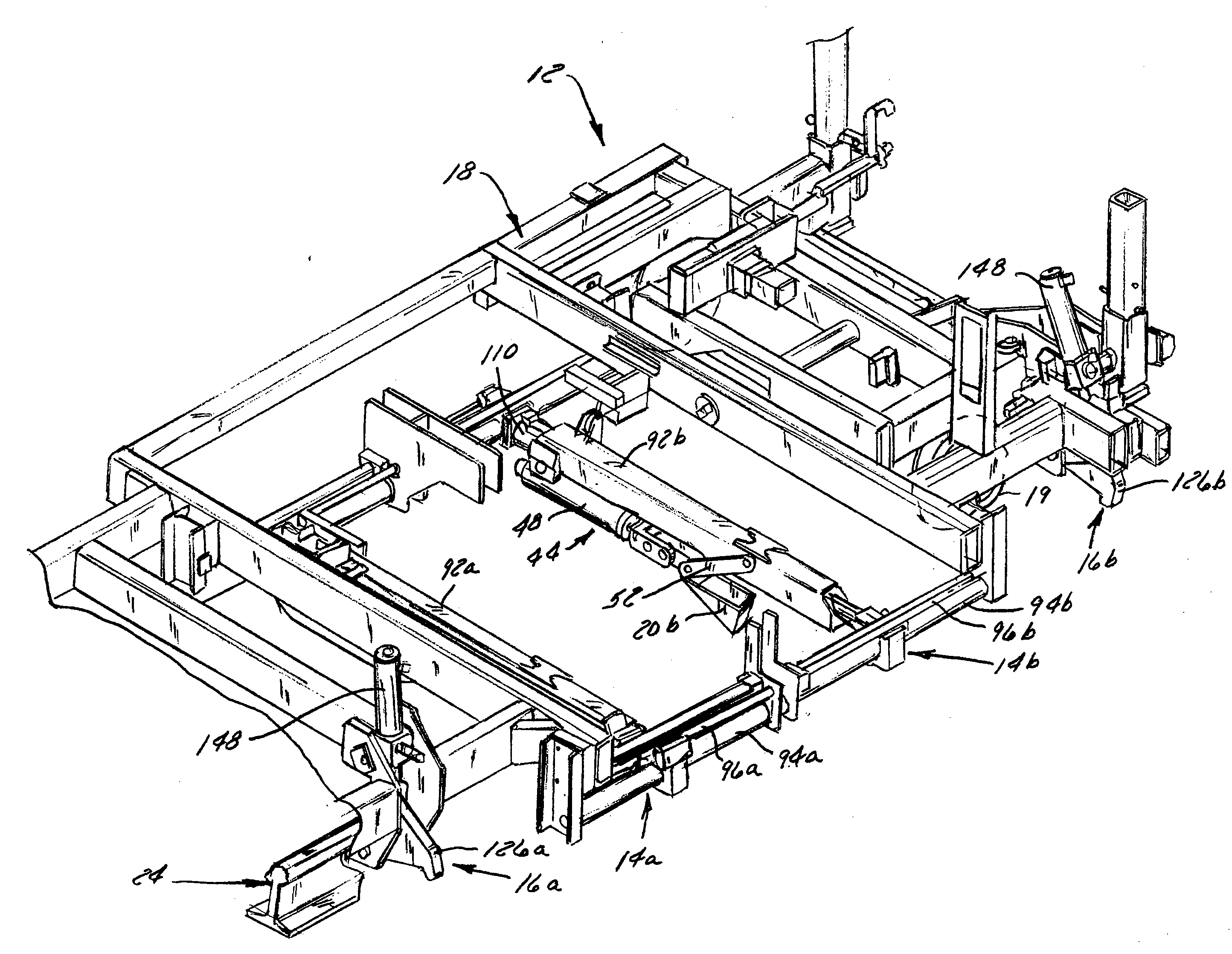
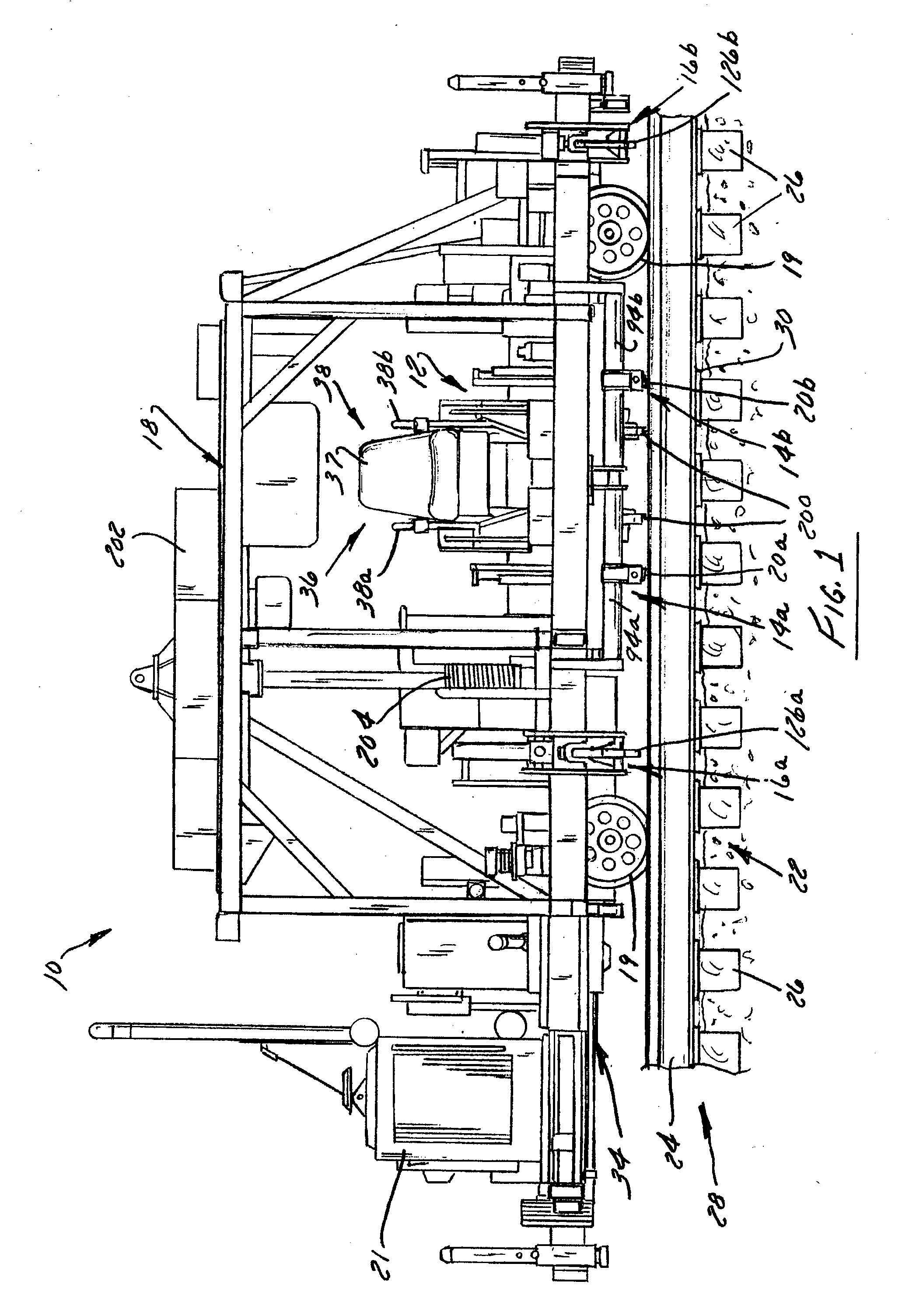
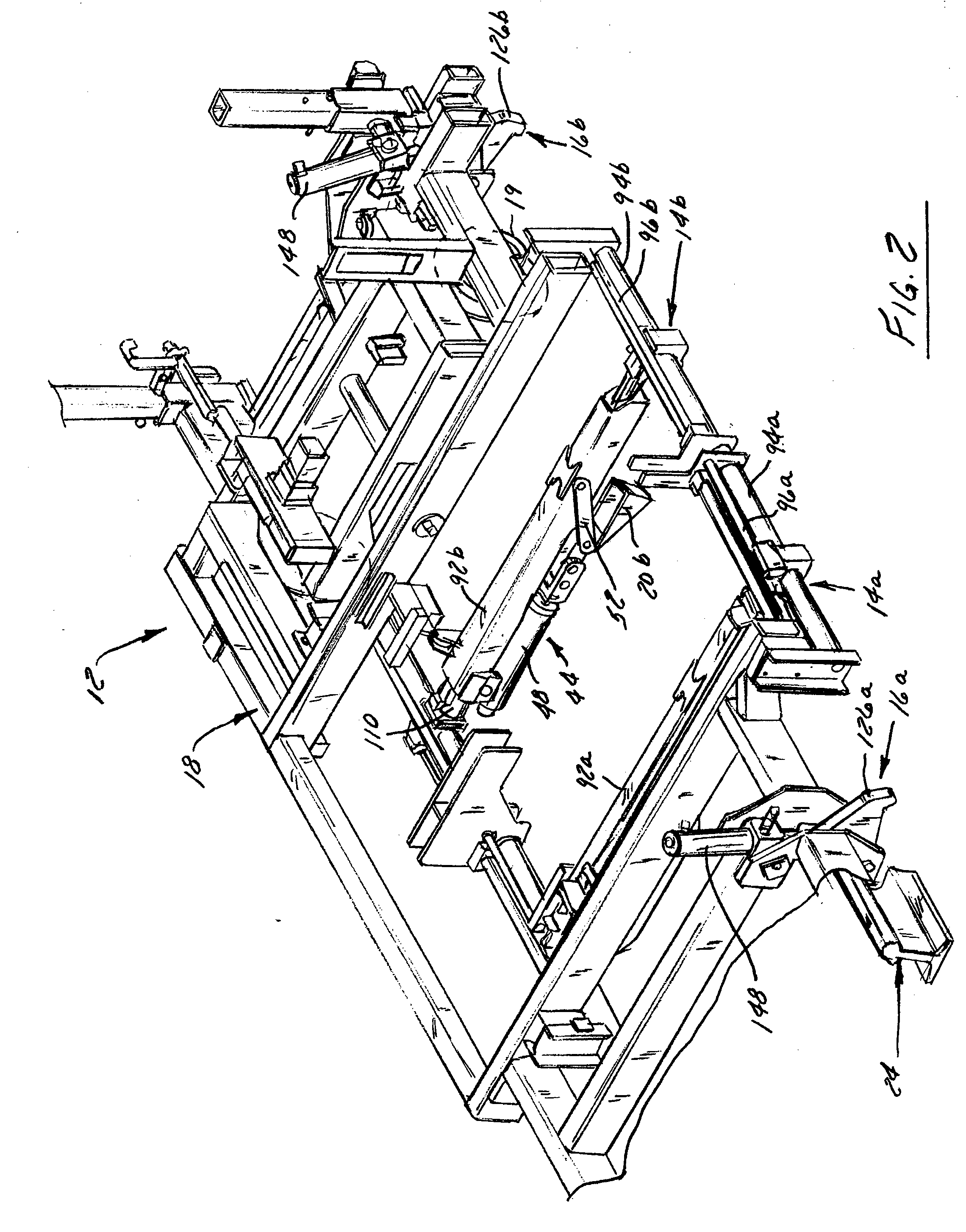
[0028]Now referring to the drawings and initially to FIG. 1, a self-propelled vehicle 10, described in more detail below, bears an anchor cribbing machine 12 according to the invention. The anchor cribbing machine 12 includes a pair of ballast cribbing assemblies 14 and a corresponding pair of rail clamp assemblies 16 supported on a fixed frame 18. The vehicle 10 of this embodiment is supported directly on the opposed rails 24 of the railway via wheels 19. However, it is conceivable that the vehicle 10 could be configured to move along a railway in which the rail opposite the rail 24 being worked has been removed, in which case the opposed side of the vehicle 10 could be supported on wheels or crawlers that are supported upon the rail bed. The vehicle 10 is powered by an engine 21 mounted on the rear of the frame 18. Two anchor applicators 200 which are, per se, well known, are mounted on the frame between the ballast cribbing assemblies. The anchor applicators 200 are manually supp...


PUM


Abstract

An anchor cribbing machine includes a pair of ballast cribbing assemblies and a pair of rail clamp assemblies. The ballast cribbing assemblies are hydraulically-driven to push ballast away from the opposing sides of a railroad tie so that an anchor may be applied to the rail at the tie location. The ballast cribbing assemblies include support beams that are movable longitudinally relative to the rails and rotatable between an operative and a stowed position. The rail clamp assemblies are configured to engage the rail to prevent the machine from being driven off the rails in operation.

Description

CROSS-REFERENCE TO RELATED APPLICATION[0001]This application claims priority to U.S. provisional application Ser. No. 61 / 561,360, filed Nov. 18, 2011, the entire contents of which are incorporated herein by reference.BACKGROUND OF THE INVENTION[0002]1. Field of the Invention[0003]The invention generally relates to railroad ballast cribbers. More particularly, the invention relates to a ballast cribber that is configured to remove the potentially-interfering ballast adjacent a railroad tie. In a particularly conferred configuration, the invention relates to an anchor cribber that can be used with an anchor applicator so as to remove ballast adjacent the tie and then apply one or more rail anchors at the railroad tie location without repositioning the anchor cribber or requiring an additional tool or machine.[0004]2. Discussion of the Related Art[0005]Anchor cribbing machines for preparing a railway for applying one or more anchors at a railroad tie location are well known in the art....

Claims


Application Information

Patent Timeline
Patent Type & Authority Applications(United States)
IPC IPC(8): E01B27/00
CPCE01B27/04E01B27/00
Inventor BRENNY, DAVID M.HON, JEFF
Owner RACINE RAILROAD PROD
Learn More