
Floating manure agitator with multidirectional agitator nozzles

a nozzle and agitator technology, applied in the field of floating vessels, can solve the problems of reducing the available volume of the storage installation area, increasing the risk of overflow, and limiting the movement of the nozzle in the vertical direction, so as to prevent damage to the pump, facilitate the effect of maneuvering, and effectively raise the floating vessel off the ground

Active Publication Date: 2018-11-06
TEWS JAMES TIMOTHY
View PDF72 Cites 5 Cited by
  • Summary
  • Abstract
  • Description
  • Claims
  • Application Information

AI Technical Summary

Benefits of technology

The present invention is related to a floating agitator vessel that is designed to improve pond management. The vessel is equipped with a low pressure, high-volume PTO pressure pump which draws effluent from the pond to feed the high pressure agitator nozzles. The use of an 8" Houle vertical super pump is contemplated for this purpose. The vessel also has a hydraulically powered undercarriage which is vertically adjustable to facilitate easy maneuvering in and out of manure pits. A remotely controllable hydraulic hitch is included to connect and disconnect the vessel from a transport vehicle without the need for manual manipulation. The vessel also has folding wings or pontoons that can be hydraulically raised and lowered for easy storage and travel. These features improve the efficiency and safety of the vessel.

Problems solved by technology

If the sludge layer is not periodically agitated and removed, it will eventually decrease the available volume of the storage installation area, thus leading to increased risk of overflows, economic and environmental concerns, etc.
While conventional floating agitators work reasonably well for their intended purpose, there are drawbacks.
However, with many floating agitators, one or more of the agitator nozzles often point directly downward from underneath the vessel, out of sight of the operator.
Other agitators include above-surface nozzles, but such nozzles are limited in movement only in the vertical direction.
This limited visibility and versatility makes directional control of the vessel extremely difficult, particularly when being operated remotely.
Maneuvering a floating agitator in and out of a manure pond or lagoon can also pose a significant challenge.
One drawback of conventional floating agitators is that they typically must be pulled out of the lagoon and loaded onto a separate trailer for hauling by a transport vehicle, such as a tractor.
Some agitators do include wheels, but such wheels are generally not adjustable relative to the floating vessel.
Consequently, the floating vessel can bottom out and become hung up on the ramp, thus loosing valuable time and potentially causing significant damage to the hull of the vessel; this is particularly the case with steep ramps leading into the lagoon.
Another drawback is that, upon launching, removing or simply transporting a conventional floating vessel to or from a manure pond, the operator(s) must manually make the connection of the vessel to a transport vehicle or trailer.
This either requires increased manpower or, at a minimum, adds time and inconvenience to the overall operation.
Still further, conventional floating vessels used in manure ponds and the like are often agitated during cold weather conditions, where ice build-up may occur on the pond.
Other than through movement of the slurry caused by the jet pumps, there is typically no means by which the vessel can break up large chunks of ice.
Thus, the floating vessel can become inhibited from free movement around the pond, making it impossible to adequately agitate the full area of the pond.
Still another drawback of conventional floating agitators is that there is typically no means by which an operator, particularly remotely, can test to determine whether the jet pumps are adequately stirring up and mixing the bottom sludge with the liquid portion of the pond.
Particularly with floating vessels having submerged output nozzles, it is difficult to determine where the nozzles are actually being aimed and whether additional sludge may have accumulated on the bottom of a certain area of the pond.
It is therefore difficult to determine whether agitation of the pond has been successfully completed, or where additional agitation would be beneficial.
Therefore, it is evident there is a substantial and unsatisfied need in the agricultural industry for a reliable and cost-effective solution to the many drawbacks associated with conventional floating manure agitators.

Method used


Image

  • Floating manure agitator with multidirectional agitator nozzles
  • Floating manure agitator with multidirectional agitator nozzles
  • Floating manure agitator with multidirectional agitator nozzles

Examples


Embodiment Construction

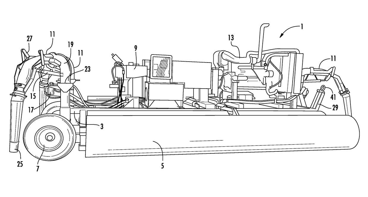
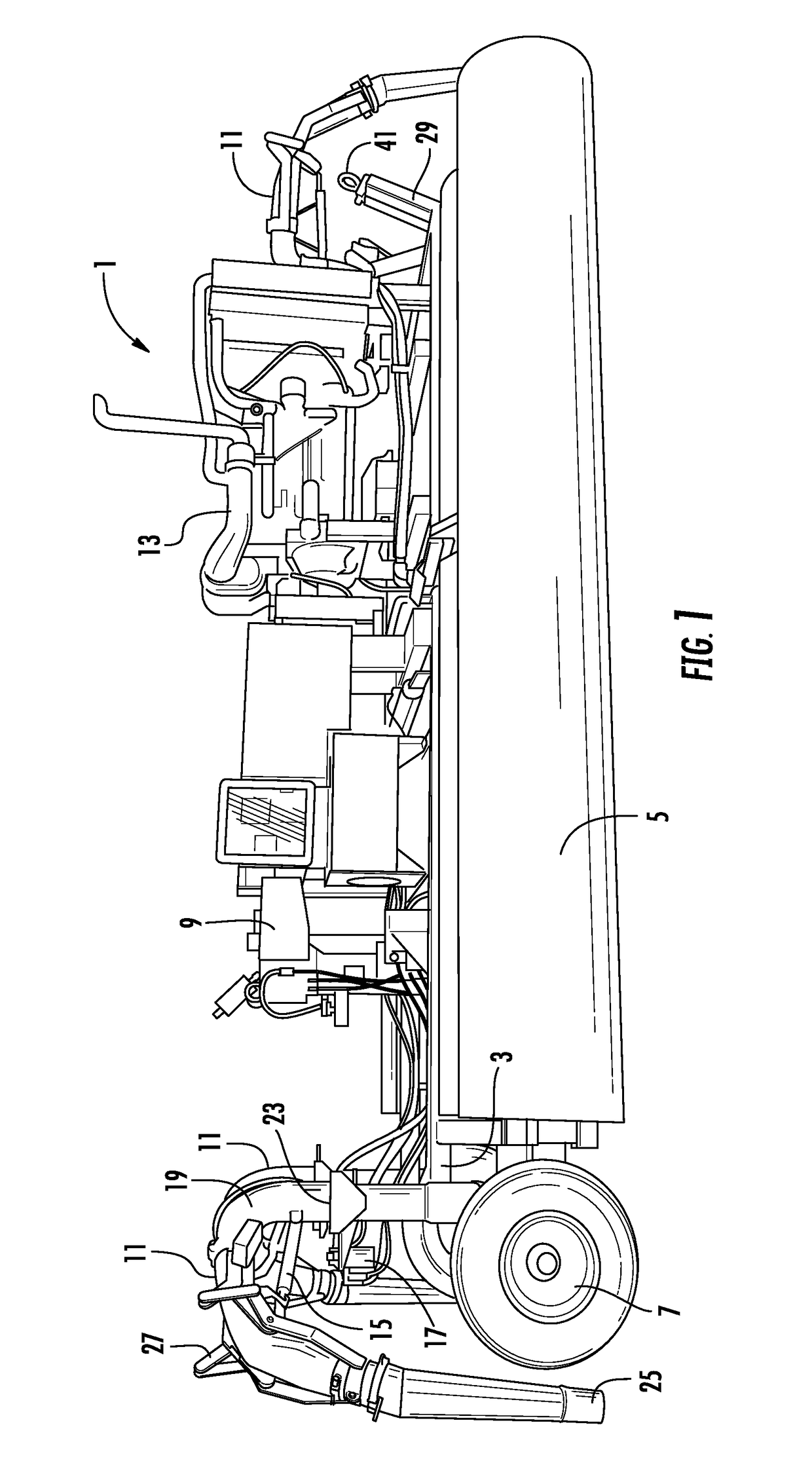
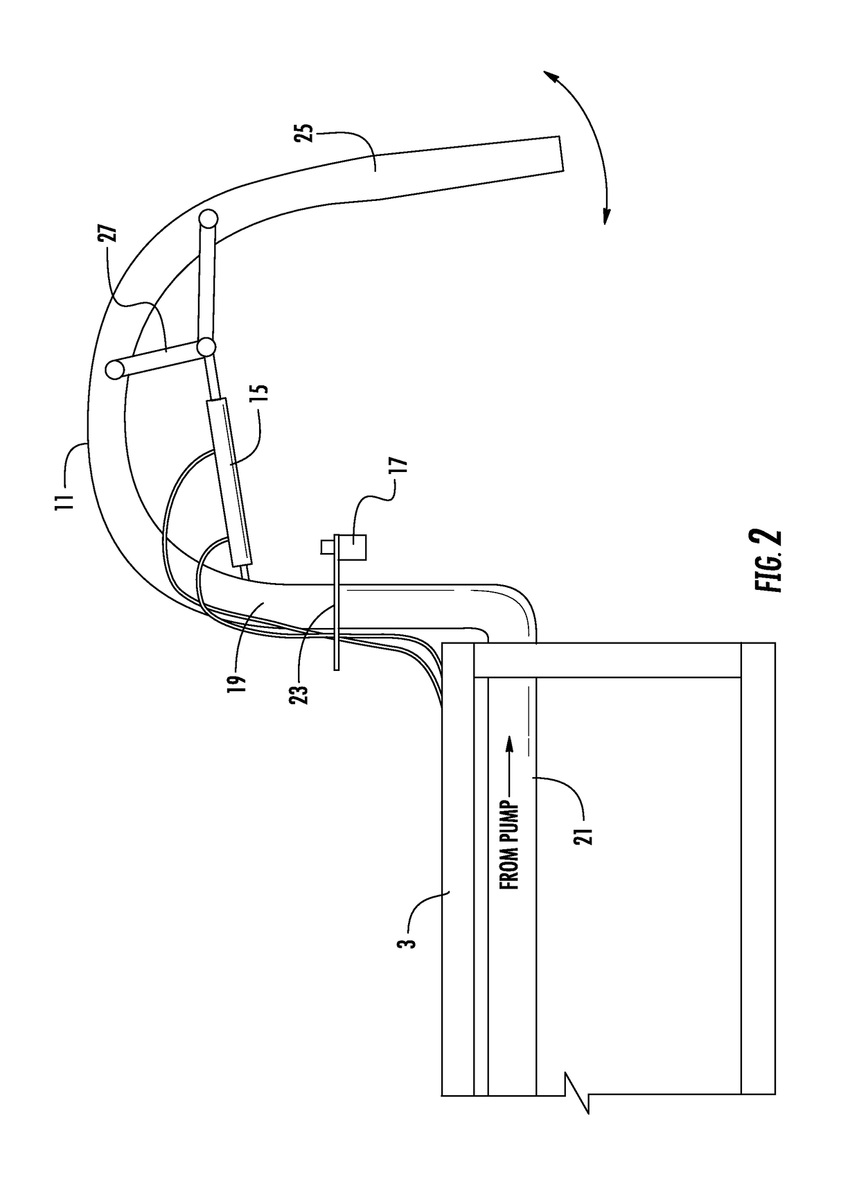
[0026]With reference to FIG. 1, a floating aquatic manure agitator vessel 1 is shown constructed in accordance with the present invention. As shown, the main body or deck 3 of the vessel is flanked on each side by a large wing 5 which functions to maintain the vessel 1 afloat in the manure pond upon launching same. Each wing 5 of the vessel extends substantially the entire length of the vessel 1 and is preferably comprised of a pair of integrally connected laterally juxtaposed pontoons. As will be described in more detail hereafter, each wing 5 is pivotally adjustable upwardly and downwardly to facilitate ease of transporting the manure agitator vessel 1. The deck 3 further includes an undercarriage system 7 with wheels to facilitate launching and removal of the vessel from the manure pond, as well as transportability and storage of the vessel.

[0027]Mounted atop of the deck 3 of the vessel 1 is a low pressure, high-volume PTO pressure pump 9 which draws effluent from the pond to fee...


PUM


Abstract

An aquatic floating manure agitator vessel including a plurality of remotely controlled above-surface agitator nozzles which are visibly positioned on the vessel and hydraulically movable about multiple axes to facilitate effective pond agitation and directional control of the floating agitator. The floating agitator includes a vertically adjustable hydraulic undercarriage and hitch mechanism to facilitate ease of maneuverability during launching and removal of the floating agitator, and for probing the pond bottom for excess sludge build-up. The floating agitator also includes hydraulically folding side wings or pontoons mounted on each side of the vessel to further enhance ease of maneuverability and storage of the vessel.

Description

TECHNICAL FIELD[0001]The present invention relates generally to the field of floating vessels and, more particularly, to a remote-controlled floating aquatic manure agitator for use in a manure earthen storage installation, such as a manure holding pond, lagoon, settling basin or other manure reservoir.BACKGROUND OF THE INVENTION[0002]The benefits of manure as a fertilizer for agricultural purposes are well known. Manure from livestock is an excellent source of fertilizer containing nitrogen, phosphorous and other nutrients desirable for enrichment of soil. Manure is also an important source of organic matter which, when added to soil, helps to improve soil composition, aeration, water infiltration and moisture-retention capability.[0003]As a necessary and inevitable by-product of the livestock industry, manure is in constant supply and a means of storage and preservation is therefore required. For this reason, earthen storage installations in the nature of holding ponds, lagoons an...

Claims


Application Information

Patent Timeline
Patent Type & Authority Patents(United States)
IPC IPC(8): B01F5/02B01F5/10B01F13/00B01F15/00
CPCB01F5/0225B01F5/025B01F5/0218B01F5/10B01F13/0049B01F15/00305B01F5/0243B01F2215/0001B01F25/2121B01F25/2124B01F25/50B01F33/503B01F25/212B01F25/2125B01F35/2205B01F2101/00
Inventor TEWS, JAMES TIMOTHY
Owner TEWS JAMES TIMOTHY
Learn More