Painting robot system and spray gun unit

a robot and spray gun technology, applied in manipulators, coatings, gripping heads, etc., can solve the problems of increasing the cost of the preparation of multiple types of spray gun units, requiring a lot of setup changes, etc., and achieve the effect of reducing the time required for setup and reducing the cost of changing the spacing between two pieces of equipmen

Active Publication Date: 2013-05-30
TOSHIBA MASCH CO LTD
View PDF3 Cites 11 Cited by
  • Summary
  • Abstract
  • Description
  • Claims
  • Application Information

AI Technical Summary

Benefits of technology

[0018]In the present invention, the rotation of the drive shaft member of the robot allows the spacing between at least one pair of the adjacent spray guns to be changed through the linkage mechanism. Cost involv

Problems solved by technology

This requires a lot of time for setup changes, including the replacement of the spray gun units.
Anot

Method used


Image

  • Painting robot system and spray gun unit
  • Painting robot system and spray gun unit
  • Painting robot system and spray gun unit

Examples


Embodiment Construction

[0034]A painting robot system according to a preferred embodiment of the present invention will be described below with reference to FIGS. 1 to 14. FIGS. 1 to 14 show a painting robot system according to the preferred embodiment of the present invention.

[0035]General arrangements of the painting robot system according to the preferred embodiment of the present invention will be described below with reference to FIGS. 1 to 3. FIGS. 1 to 3 show the painting robot system according to the preferred embodiment of the present invention.

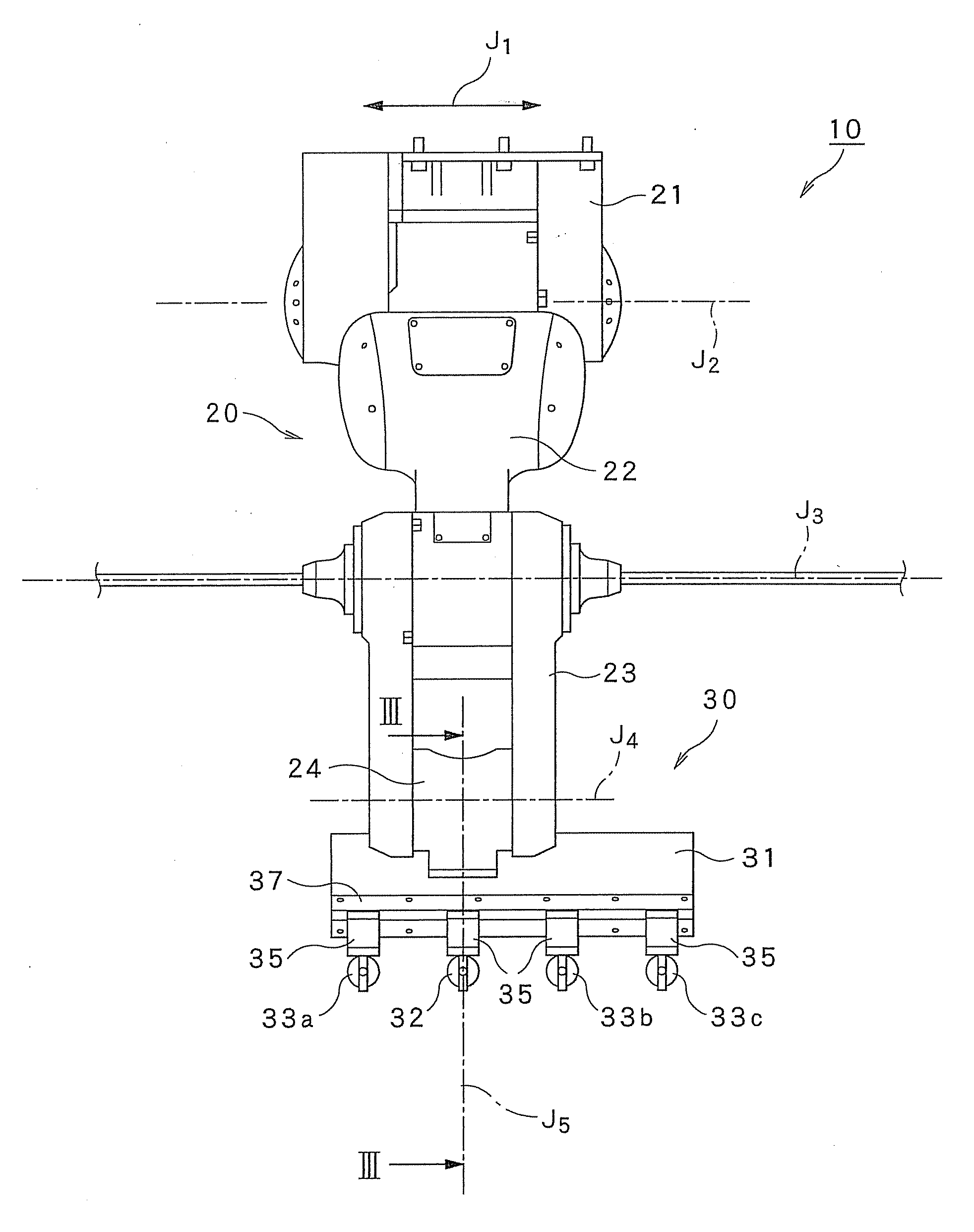
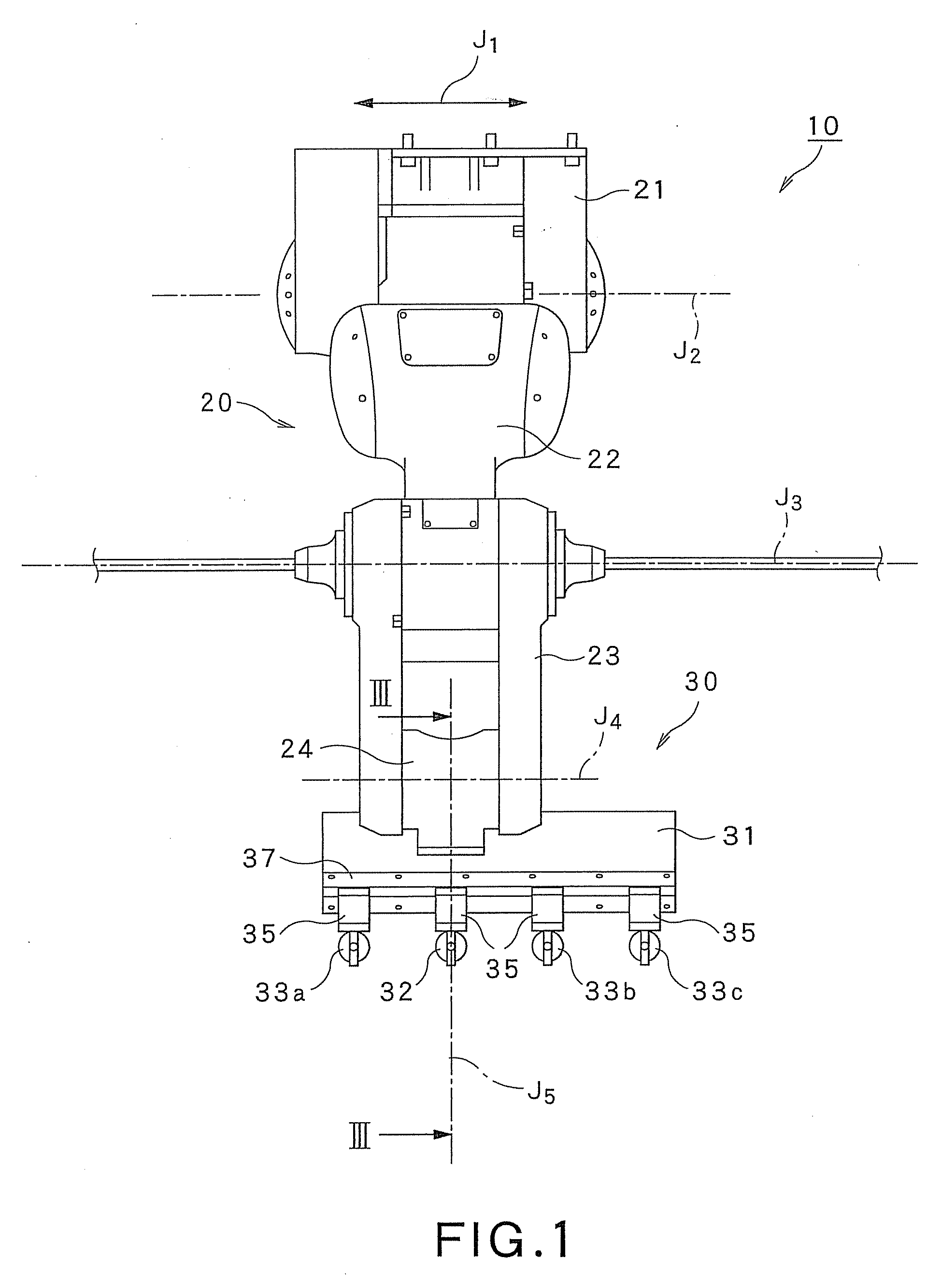
[0036]Referring to FIGS. 1 and 2, a painting robot system 10 includes a robot 20 and a spray gun unit 30. The robot 20 includes a base section 21 and a plurality of robot arms 22 to 24. The spray gun unit 30 is attached to the robot arm (a third robot arm) 24 at a distal end of the robot 20.

[0037]The robot 20 includes the base section 21 that is horizontally movable along a first drive axis J1 and the three robot arms (a first robot arm 22, a second robot a...


PUM


Abstract

A painting robot system includes a robot and a spray gun unit. The robot includes a plurality of robot arms and a drive shaft member disposed on a distal end robot arm of the multiple robot arms, the drive shaft member being rotatable about a distal end drive axis. The spray gun unit is mounted on the robot arm. The spray gun unit includes a support member fixed to the distal end robot arm, guide members disposed on the support member, a plurality of spray guns disposed on the support member, and a linkage mechanism connecting between the movable spray guns and the drive shaft member. A spacing between at least one pair of adjacent spray guns can be varied via the linkage mechanism by rotating the drive shaft member of the robot.

Description

CROSS-REFERENCE TO RELATED APPLICATION [0001]This application claims the benefit of Japanese Patent Application No. 2011-249031, filed on Nov. 14, 2011, which is incorporated herein by reference.BACKGROUND OF THE INVENTION [0002]1. Field of the Invention[0003]The present invention relates to a painting robot system, and a spray gun unit incorporated in such a painting robot system.[0004]2. Description of the Related Art[0005]Known approaches to painting an article to be painted, such as a compact portable terminal, employ a robot for painting the article to be painted that is set up in a rotary jig. Others include a plurality of spray guns attached to a robot arm to achieve enhanced painting efficiency (see JP-A-2010-120148).SUMMARY OF THE INVENTION [0006]In the known common painting systems, however, a predetermined spacing (pitch) is established between the articles to be painted. As a result, when the spacing between the articles to be painted is changed, the paint job needs to b...

Claims


Application Information

Patent Timeline
IPC IPC(8): B05B15/08B05B15/68
CPCB05B13/0431B05B15/08B05B15/68B05B15/60B25J11/0075B25J15/0019B25J15/0052B05C5/0216B05C5/0295B05C15/00
Inventor UEMATSU, TEPPEINEGISHI, YUJI
Owner TOSHIBA MASCH CO LTD
Why Eureka
Try Eureka