
Electronically commutated motor

a technology of electric commutation and motor, which is applied in the direction of electronic commutators, dynamo-electric machines, and commutation monitoring. it can solve the problems of low efficiency, high noise, and large energy consumption of conventional permanent split capacitor (psc) motors, and achieves convenient wiring, simple structure, and easy substitution.

Active Publication Date: 2016-06-14
ZHONGSHAN BROAD OCEAN
View PDF4 Cites 0 Cited by
  • Summary
  • Abstract
  • Description
  • Claims
  • Application Information

AI Technical Summary

Benefits of technology

[0011]In view of the above-described problems, it is one objective of the invention to provide an ECM that has a simple structure and is adapted to substitute for a PSC and existing ECMs with 24 VAC as a gear input signal. The substitution is easy, the wiring is convenient, the involved cost is low, the signal coupling is prevented, and the safety and reliability are high.
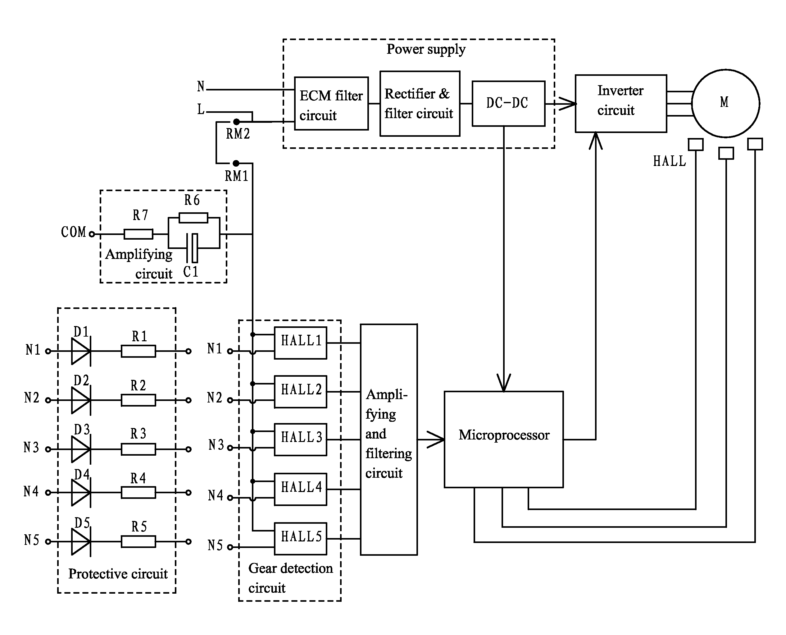
[0022]1) The invention provides an ECM comprising: a motor body and a motor controller. The motor controller comprises a control box and a circuit board disposed in the control box. The circuit board comprises a microprocessor, an inverter circuit, a gear detection circuit, and a power supply. The microprocessor, the inverter circuit, the gear detection circuit, and the power supply are all integrated on the circuit board; the gear detection circuit comprises a plurality of current sensing units. An output end of the power supply supplies power to each circuit, and a first AC input end of the power supply is connected to a first power input line N. The gear detection circuit is connected to a plurality of gear input lines; at least one of the gear input lines is selected to be in an energized state. Each gear input line is correspondingly connected to a first input end of one of the current sensing units. An output end of each current sensing unit is connected to an input end of the microprocessor. The microprocessor selects operating parameters of the motor according to a detected signal of an energization state of each gear input line and controls the motor to operate according to selected operating parameters. The current sensing units detect signals from the gear input lines, and the signals are a 24 V low voltage AC signal or a 115 V or 230 V high voltage AC signal. When the 115 V or 230 V high voltage AC signal is input from the gear input lines, a second AC input end of the power supply is connected to a second power input line L, and a second input end of the current sensing units is in parallel connection to the second AC input end of the power supply and is connected to the second power input line L. When the 24 V low voltage AC signal is input from the gear input lines, the second AC input end of the power supply is connected to the second power input line L, and the second AC input end of the power supply is in parallel connection to the second AC input end of the power supply and is connected to a common lead COM; the 24 V low voltage AC signal is input into the gear input lines via a protective circuit; the protective circuit comprises a plurality of circuit protection units, each circuit protection unit is connected to one corresponding gear input line, and each circuit protection unit comprises at least a diode. The ECM has a simple structure and is adapted to substitute for a PSC and existing ECMs with 24 VAC as gear input signal. The substitution is easy, the wiring is convenient, the involved cost is low, the signal coupling is prevented, and the safety and reliability are high.
[0023]2) When the 24 V low voltage AC signal is input from the gear input lines, the second AC input end of the power supply is connected to the second power input line L, and the second AC input end of the power supply is in parallel connection to the second AC input end of the power supply and is connected to the common lead via an amplifying circuit. Thus, the gear input lines can obtain stronger current signals, the microprocessor can precisely judge whether the gear signals are effective, thereby ensuring the precise and reliable control.
[0024]3) Each circuit protection unit further comprises a resistor which is in series connection to the diode. Resistances of the resistors of the circuit protection units are unequal so as to form different energization signals input to the gear input lines; when at least two gear input lines are in an energization state, the microprocessor compares energization signal values of the gear input lines and controls the motor to operate according to a gear outputting a biggest energization signal. Thus, the control is reliable, and the gear outputting the biggest energization signal can operate in advance.
[0025]4) The second AC input end of the power supply is in parallel connection to the second AC input end of the power supply and then connected to the second power input line L via a connection terminal through short-circuit connection. Thus, the connection is convenient and reliable.
[0026]5) The circuit protection units employ a hall current sensor unit, which has a small volume and low cost, and can effectively improve the heat dispersion of the motor controller. An output terminal of the hall current sensor unit is connected to the microprocessor via an amplifying and filtering circuit, which can effectively reduce the current fluctuation at the output end of the gear detection circuit, and improve the precision and reliability of the detection of the microprocessor.

Problems solved by technology

Conventional permanent-split capacitor (PSC) motors consume a large amount of energy, produce much noise, and have low efficiency.
1) The function of the ECM motor is single and not applicable to different workplaces, for example, operating parameters like the supply voltage cannot be directly set;
2) Conventionally, when an ECM is substituted for a PSC motor, a current sensor is serially connected to the input terminal of the gears; and the gears are in electric connection to one another. When an ECM controlled by a 24 VAC signal is replaced, signal coupling tends to occur, the heating wires tend to malfunction which is a hidden danger;
3) When an ECM controlled by a 24 VAC signal is replaced, the current signal flowing in the current sensor at the input terminal of the motor is weak, and it is difficult to determine whether the gear signals are effective;
4) The state of each gear input line is detected by a current transformer and related circuits, however, the current transformer has a large volume and high product costs and occupies relatively large space of the motor controller, thereby decreasing the heat dissipation of the motor controller; and
5) A plurality of sensing units of the current transformer are embedded in a wiring plug of the motor, the installation of which is difficult, thereby lowering the production efficiency and making large scale production difficult.

Method used


Image

  • Electronically commutated motor
  • Electronically commutated motor
  • Electronically commutated motor

Examples


Embodiment Construction

[0031]For further illustrating the invention, experiments detailing an electronically commutated motor (ECM) are described below. It should be noted that the following examples are intended to describe and not to limit the invention.

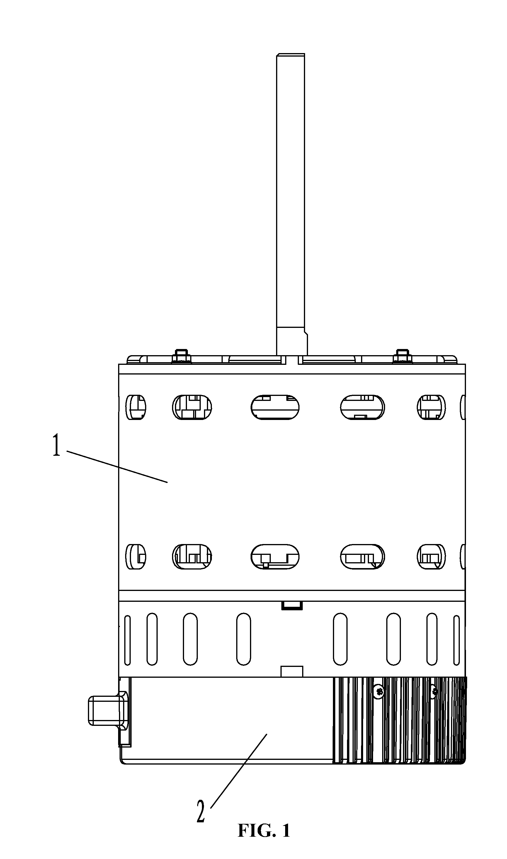
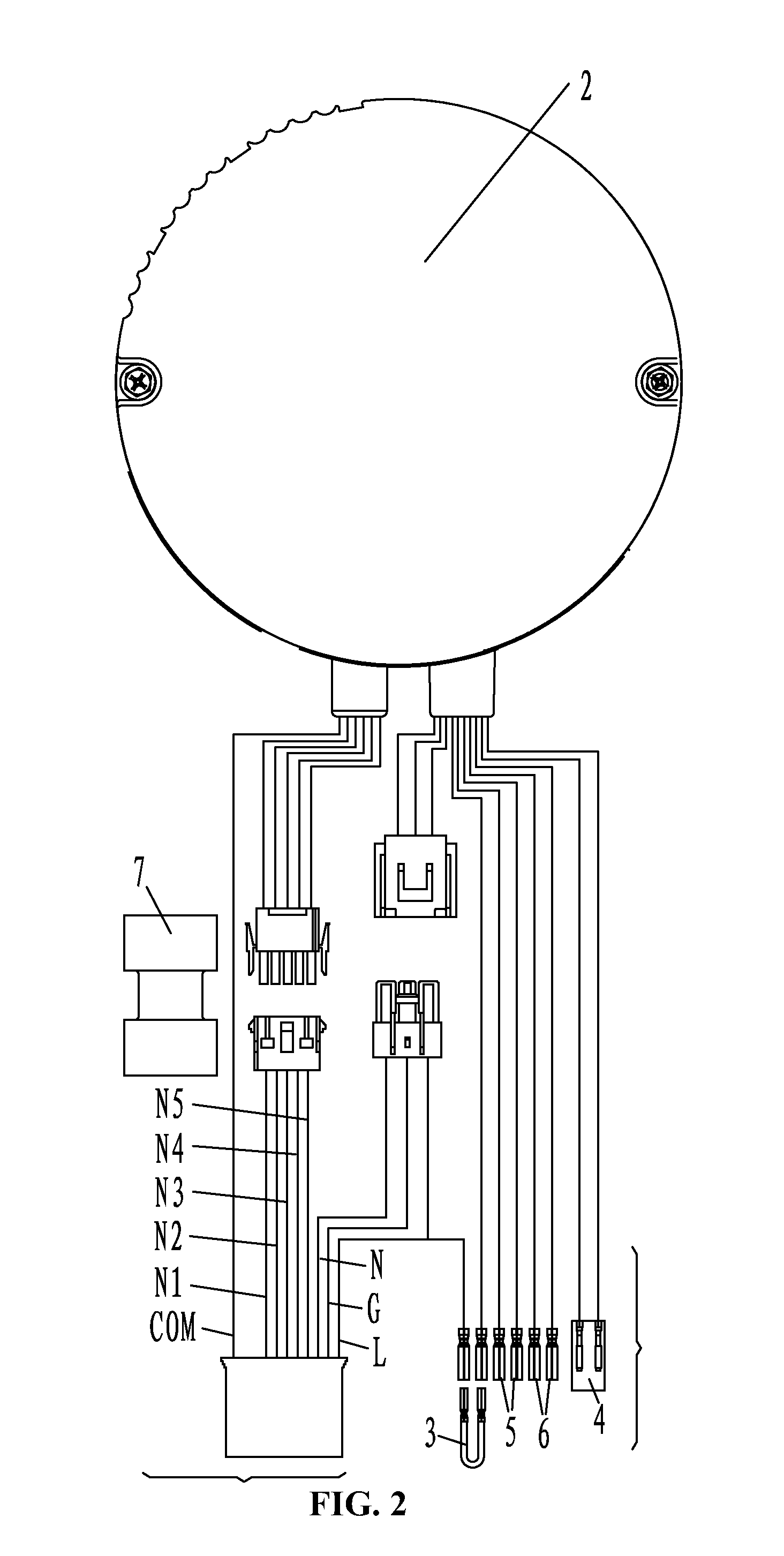
[0032]As shown in FIGS. 1-3, an electronically commutated motor (ECM) comprises: a motor body 1 and a motor controller 2. The motor controller comprises a control box and a circuit board disposed in the control box. The circuit board comprises a microprocessor, an inverter circuit, a gear detection circuit, and a power supply. The power supply comprises an ECM filter circuit, a rectifier & filter circuit, and a DC-DC transfer circuit; an input end of the ECM filter circuit is connected to an AC input, and an output end of the ECM filter circuit is connected to an input end of the rectifier & filter circuit; the rectifier & filter circuit outputs a busbar voltage and is connected to the DC-DC transfer circuit, the DC-DC transfer circuit output a voltage o...


PUM


Abstract

An electronically commutated motor, including: a motor body and a motor controller. The motor controller includes a control box and a circuit board disposed in the control box. The circuit board includes a microprocessor, an inverter circuit, a gear detection circuit, and a power supply. The gear detection circuit includes a plurality of current sensing units. The output end of the power supply supplies power to each circuit, and a first AC input end of the power supply is connected to a first power input line N. The gear detection circuit is connected to a plurality of gear input lines. At least one of the gear input lines is selected to be in an energized state. Each gear input line is correspondingly connected to a first input end of one of the current sensing units.

Description

CROSS-REFERENCE TO RELATED APPLICATIONS[0001]Pursuant to 35 U.S.C. §119 and the Paris Convention Treaty, this application claims the benefit of Chinese Patent Application No. 201420427025.5 filed Jul. 30, 2014, the contents of which are incorporated herein by reference. Inquiries from the public to applicants or assignees concerning this document or the related applications should be directed to: Matthias Scholl P.C., Attn.: Dr. Matthias Scholl Esq., 245 First Street, 18th Floor, Cambridge, Mass. 02142.BACKGROUND OF THE INVENTION[0002]1. Field of the Invention[0003]The invention relates to an electronically commutated motor (ECM).[0004]2. Description of the Related Art[0005]Conventional permanent-split capacitor (PSC) motors consume a large amount of energy, produce much noise, and have low efficiency. Permanent magnet synchronous motors, such as, e.g., ECM motors, are provided with a motor controller, so that they have high reliability, high controllability, and low noise. It is a ...

Claims


Application Information

Patent Timeline
Patent Type & Authority Patents(United States)
IPC IPC(8): H02H7/08H02K11/00
CPCH02K11/001H02K11/0073H02P6/08H02P6/16H02P6/12H02K11/33H02K11/20H02P6/14
Inventor ZHAO, YONGCHEN, YUNSHENGBIAN, WENQINGWU, YONGHUA
Owner ZHONGSHAN BROAD OCEAN
Learn More