Method for operating an exhaust after-treatment system comprising an SCR-catalyst

an exhaust aftertreatment and scrcatalyst technology, which is applied in the direction of exhaust treatment, engine components, mechanical equipment, etc., can solve the problem of insufficient reserv

Active Publication Date: 2020-12-15
ROLLS ROYCE SOLUTIONS GMBH
View PDF19 Cites 0 Cited by
  • Summary
  • Abstract
  • Description
  • Claims
  • Application Information

AI Technical Summary

Benefits of technology

[0038]Alternatively or additionally, it is also possible that a current value for the changed determining parameter in the first adaptation period is recorded in the overwritable characteristic map, and is then provided in the second adaptation period. In this case, the current value for the changed determining parameter can also be used as an item of data for determination of the adaptation parameter, especially when the current value for the changed determining parameter in each case is calculated from a predetermined, fixed initial value for the determining parameter and the current adaptation parameter. In this case, the adaptation parameter can be determined by means of simple calculation of the current, changed determining parameter with the predetermined, fixed determining parameter.
[0039]The use of an overwritable characteristic map, especially a learning characteristic map, also makes it possible to use, for the target nitrogen oxide concentration downstream of the SCR catalyst, as determining parameter, a predetermined characteristic map which is fixed, i.e. constant over time, from which, especially in an operating point-dependent manner, the predetermined, fixed initial value for the determining parameter is read off in each case and is then computed together with the adaptation parameter for calculation of the current, changed determining parameter. This has the advantage that the characteristic map of the initial values is always preserved, with the possibility of direct access to these initial values again—especially after exchange of an SCR catalyst.

Problems solved by technology

Thus, it is also possible to react flexibly to excessive aging of the system in operation, for which any design reserve may be insufficient.

Method used


Image

  • Method for operating an exhaust after-treatment system comprising an SCR-catalyst
  • Method for operating an exhaust after-treatment system comprising an SCR-catalyst
  • Method for operating an exhaust after-treatment system comprising an SCR-catalyst

Examples


Embodiment Construction

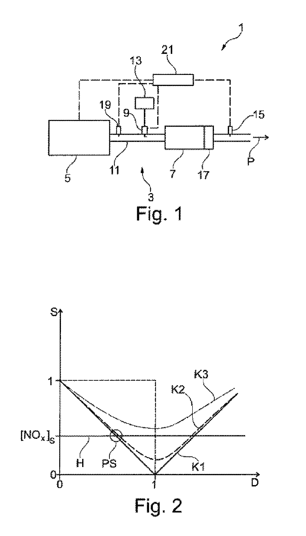
[0079]FIG. 1 shows a schematic diagram of a working example of an internal combustion engine 1 having an exhaust gas aftertreatment system 3. The internal combustion engine 1 especially has an engine block 5, wherein exhaust gas emitted by the engine block 5 can flow through the exhaust gas aftertreatment system 3 and—as shown by an arrow P—further to an outlet or exhaust which is not shown. The exhaust gas aftertreatment system 3 has an SCR catalyst 7 set up for selective catalytic reduction of nitrogen oxides. In addition, the exhaust gas aftertreatment system 3 has a dosage unit 9 for dosage of a reducing agent or a reducing agent precursor product into an exhaust gas pathway 11 of the exhaust gas aftertreatment system 3, wherein the dosage unit 9 is arranged upstream of the SCR catalyst 7. The dosage unit 9 is in fluid connection to a reservoir 13, wherein a reducing agent or a reducing agent precursor product, especially a urea / water solution, can be conveyed from the reservoir...


PUM


Abstract

A method for operating an exhaust after-treatment system including an SCR-catalyst, a metering device for dosing a reducing agent being controlled on the basis of a determining variable that influences a nitrogen-oxide concentration downstream of the SCR-catalyst. A breakthrough identification is carried out for the SCR-catalyst, wherein if a breakthrough is identified, the determining variable is altered to a higher nitrogen-oxide concentration downstream of the SCR-catalyst and the metering device is controlled in order to dose the reducing agent on the basis of the altered determining variable.

Description

[0001]The present application is a 371 of International application PCT / EP2016 / 001093, filed Jun. 28, 2016, which claims priority of DE 10 2015 212 697.8, filed Jul. 7, 2015, the priority of these applications is hereby claimed and these applications are incorporated herein by reference.BACKGROUND OF THE INVENTION[0002]The invention relates to a method of operating an exhaust gas aftertreatment system, to a control unit for an exhaust gas aftertreatment system, to an exhaust gas aftertreatment system, and to an internal combustion engine.[0003]Exhaust gas aftertreatment systems comprising at least one catalyst for selective catalytic reduction of nitrogen oxides (SCR catalyst) are used to reduce nitrogen oxide emissions to legally stipulated values. Over a service life of the exhaust gas aftertreatment system, it is possible that the maximum conversion rate that such an SCR catalyst can achieve will decrease. A typical design of an exhaust gas aftertreatment system takes account of ...

Claims


Application Information

Patent Timeline
Patent Type & Authority Patents(United States)
IPC IPC(8): F01N3/20F01N11/00
CPCF01N3/208F01N11/00F01N2610/02F01N2550/02F01N2900/0402F01N2560/026Y02T10/12Y02T10/40F01N2590/08F01N2590/02F01N2590/10
Inventor RUSCH, KLAUSREMELE, JÖRGNIEMEYER, JENS
Owner ROLLS ROYCE SOLUTIONS GMBH
Why Eureka
Try Eureka