Safety Belt for a Vehicle

a seat belt and vehicle technology, applied in the field of seat belts for vehicles, can solve the problems of high gas pressure acting internally on the seat belt, and achieve the effects of minimizing the risk of injury to the vehicle occupant(s), reducing the deflection point, and reducing the amount of gas to be introduced into the interior of the seat bel

Active Publication Date: 2013-05-30
DAIMLER AG
View PDF4 Cites 11 Cited by
  • Summary
  • Abstract
  • Description
  • Claims
  • Application Information

AI Technical Summary

Benefits of technology

[0022]If the latch plate is inserted into the buckle and at a minimum pay-out length of the belt webbing, the tube preferably extends no further than an upper deflection point. This means that the tube, if the seat belt is fastened, extends no further than the upper deflection point, which is preferably located in the upper region next to the vehicle occupant or the vehicle seat. In addition, the inflatable belt interior extends no further than the upper deflection point in the shoulder belt region at a minimum pay-out length. In this way, an inflation of the belt webbing behind the upper deflection point is avoided. As a result, the gas quantity to be introduced into the belt interiors is minimized. In addition, any deformation of, damage to or loosening of paneling within the vehicle, behind which the belt webbing runs, is avoided, so that the risk of injury to the vehicle occupant(s) is minimized.
[0023]In a further embodiment, the tube is directly coupled to the gas generator, thereby forming a so-called gas lance. This advantageously results in a further improvement of the unfolding of the tube and consequently of the belt webbing, in particular in a shortening of the time leading to the unfolding.
[0024]The width of the belt webbing is preferably divided into several parts of approximately equal width, the belt webbing being folded once or several times parallel to its longitudinal dimension. In the region of the interior folded layers, the belt webbing is preferably woven thinner than in the region of the two outer folded layers. As a result, the belt webbing has an advantageously minimal thickness, a high flexibility and a low weight.
[0025]The folded layers

Problems solved by technology

One disadvantage of these known inflatable seat belts is that during the inflation process high gas pressures act

Method used


Image

  • Safety Belt for a Vehicle
  • Safety Belt for a Vehicle
  • Safety Belt for a Vehicle

Examples


Embodiment Construction

[0034]Corresponding parts are identified by the same reference numbers in all figures.

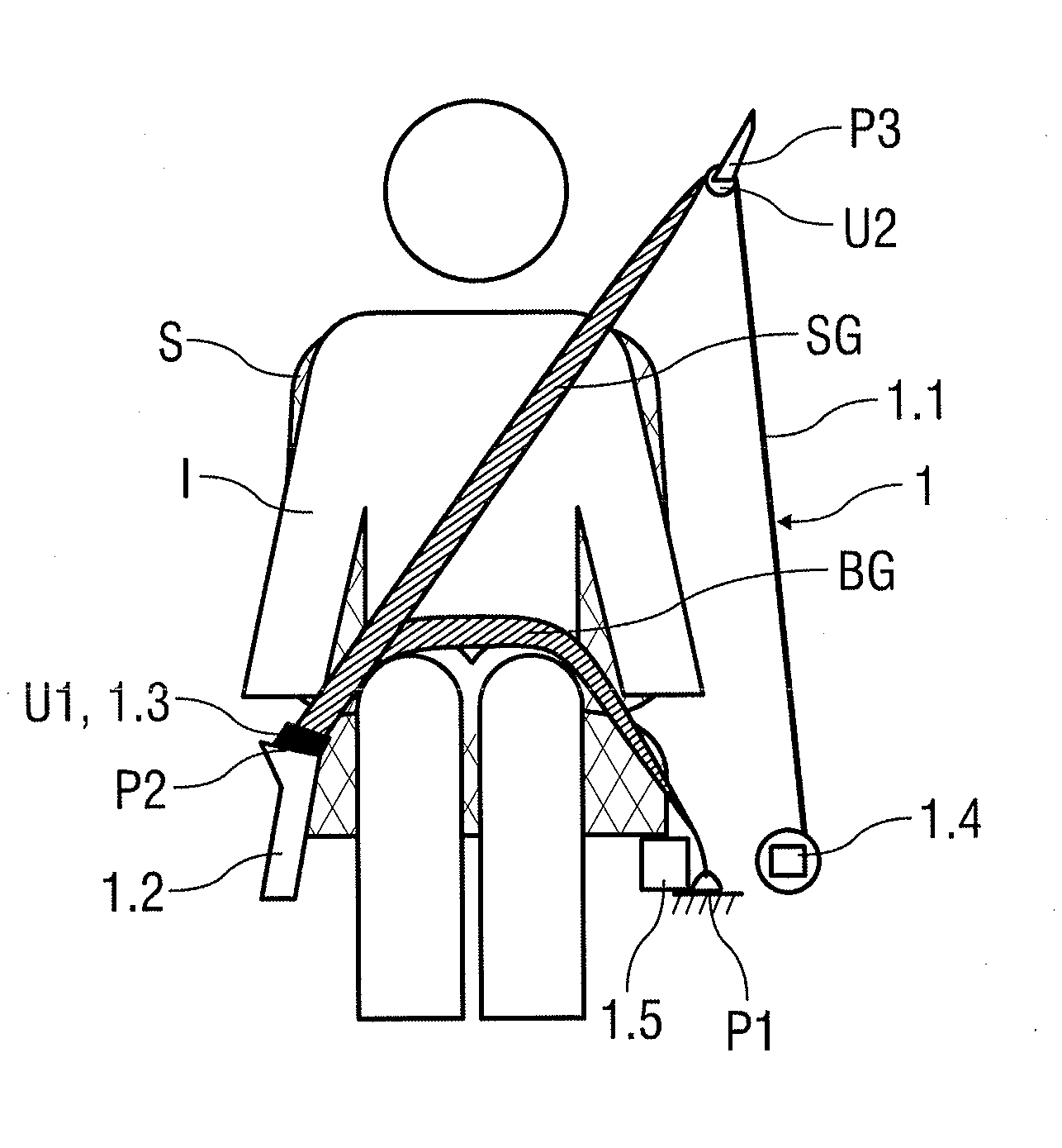
[0035]In FIG. 1, a vehicle occupant I is shown on a vehicle seat S, the vehicle occupant I wearing a seat belt 1 according to the invention. The seat belt 1 is a so-called three-point belt, which ties the vehicle occupant to a vehicle body at three points P1 to P3.

[0036]A first point P1 is located in the lower region next to the vehicle seat S, in particular on a B-post of the vehicle. At this first point P1, a belt webbing 1.1 of the seat belt 1 is secured to the vehicle body.

[0037]From this first point P1, the belt webbing 1.1 is routed via a lap region of the vehicle occupant I to a second point P2, which is represented by a buckle 1.2 secured to the vehicle body and preferably including an integrated tensioner (not shown in the drawing). A so-called latch plate 1.3 engages the buckle 1.2 or is tied thereto. The region of the belt webbing 1.1 running across the lap region of the vehicle occupant...


PUM


Abstract

A seat belt for a vehicle includes a belt webbing with several belt webbing layers and, in a shoulder belt region and a lap belt region, a belt interior located between at least two belt webbing layers to which a gas can be applied. The belt webbing is routed through an opening of a latch plate which is insertable into a buckle, by means of which latch plate the belt webbing is, if the seat belt is fastened, deflected at a lower deflection point in a transitional region from the lap belt region to the shoulder belt region. A gas passage connecting at least two sections of the belt interior is provided at the lower deflection point between the at least two belt webbing layers. The gas passage is a tube that is flexible at least in the radial direction. The flexible tube is plastically or elastically deformable.

Description

BACKGROUND AND SUMMARY OF THE INVENTION[0001]Exemplary embodiments of the present invention relate to a seat belt for a vehicle, comprising a belt webbing that comprises several belt webbing layers and, in a shoulder belt region and a lap belt region, at least one belt interior which is located between at least two belt webbing layers and to which a gas can be applied, wherein the belt webbing is guided through an opening of a latch plate which can be inserted into a buckle, by means of which latch plate the belt webbing is, if the seat belt is fastened, deflected at a lower deflection point in a transitional region from the lap belt region to the shoulder belt region, and wherein a gas passage connecting at least two sections of the belt interior is provided at the lower deflection point between the at least two belt webbing layers.[0002]German Patent Document DE 91 03 845 U1 discloses a restraint device for occupants of a vehicle. The restraint device comprises a seat belt with a ...

Claims


Application Information

Patent Timeline
IPC IPC(8): B60R21/18
CPCB60R21/18B60R22/023B60R21/2342
Inventor BURCZYK, CHRISTIAN
Owner DAIMLER AG
Why Eureka
Try Eureka