Low bend loss optical fiber

a technology of optical fibers and microbends, applied in the direction of optical waveguide light guides, glass optical fibres, instruments, etc., can solve the problems of high cost of coatings, difficult in some optical fiber designs to achieve simultaneous low bend loss, and inconvenient installation of coatings

Active Publication Date: 2013-05-30
CORNING INC
View PDF2 Cites 39 Cited by
  • Summary
  • Abstract
  • Description
  • Claims
  • Application Information

AI Technical Summary

Benefits of technology

[0008]One embodiment of the disclosure relates to a single mode optical fiber comprising: (I) a central core region having outer radius r1 and refractive index Δ1, with a maximum refractive index Δ1max and an alpha (α) profile where 1≦α≦100; (II) a cladding region comprising (a) a first inner cladding region having outer radius r2

Problems solved by technology

It has been difficult in some optical fiber designs to simultaneously achieve low bend loss, low cable cutoff wavelength, and a zero dispersion wavelength between 1300 nm and 1324 nm.
More specifically, it is known that standard single mode fibers t

Method used


Image

  • Low bend loss optical fiber
  • Low bend loss optical fiber
  • Low bend loss optical fiber

Examples


examples 1-23

Fiber Examples 1-23

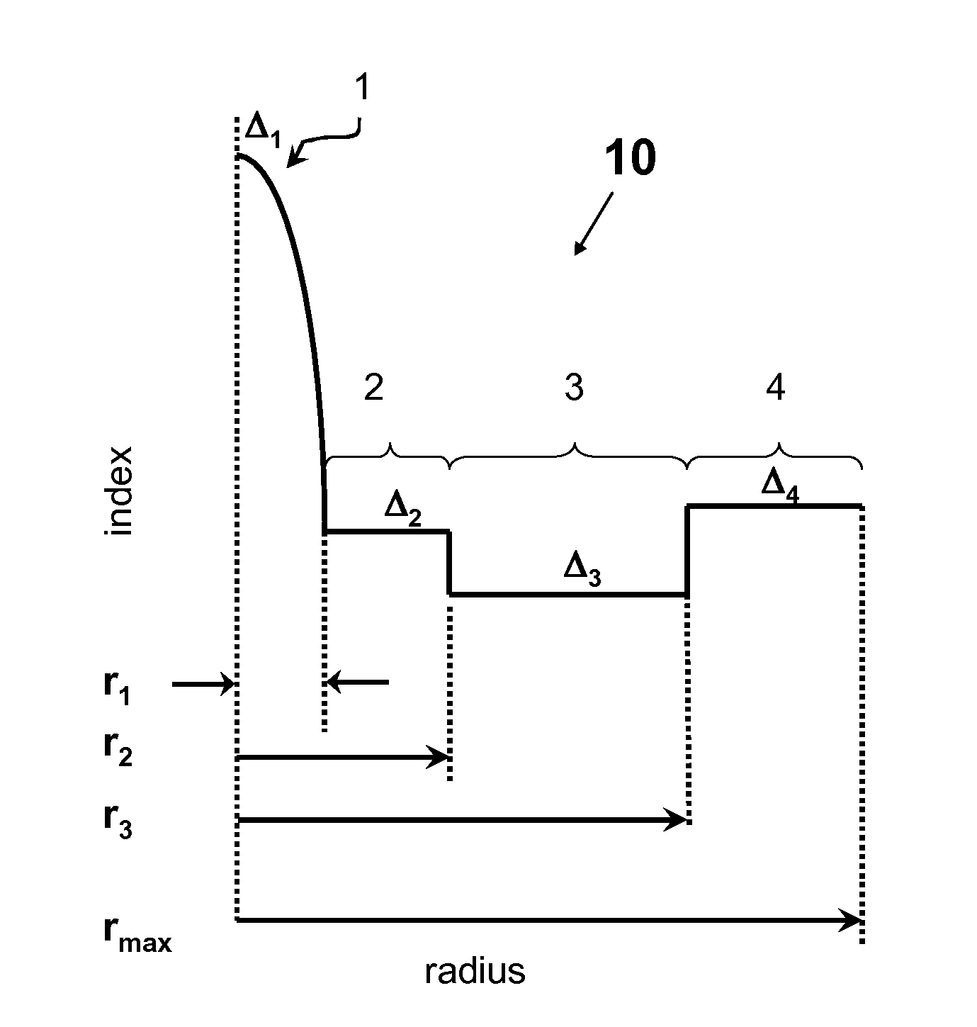
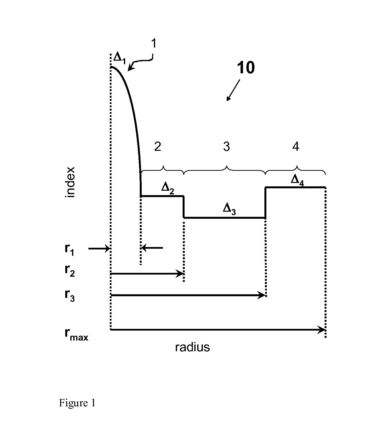
[0049]Tables 1A-1C below list characteristics of modeled illustrative examples 1-23 having a refractive index profile similar to that shown in FIG. 1. In particular, set forth below for each example is the refractive index delta Δ1max, alpha1, and outer radius R1 of the central core region 1, refractive index delta Δ2, alpha2, and outer radius R2 inner cladding region 2, refractive index delta Δ3 and volume V3 of the inner cladding region 3, refractive index delta Δ4, R4 and volume V4 of the outer cladding region 4, which is calculated between inner radius R3 of outer cladding region 3 and a radial distance of 30 microns (and between the refractive index Δ4 and that of Δ3). Also set forth are r1 / r2, theoretical cutoff wavelength in nm of LP01 and LP11 modes, mode field diameter in microns at 1310 nm, chromatic dispersion at 1310 nm in (ps / nm / km), dispersion slope at 1310 nm in (ps / nm2 / km), zero dispersion wavelength, λ0 in (nm), mode field diameter at 1550 nm in m...

examples 24-25

Fiber Examples 24-25

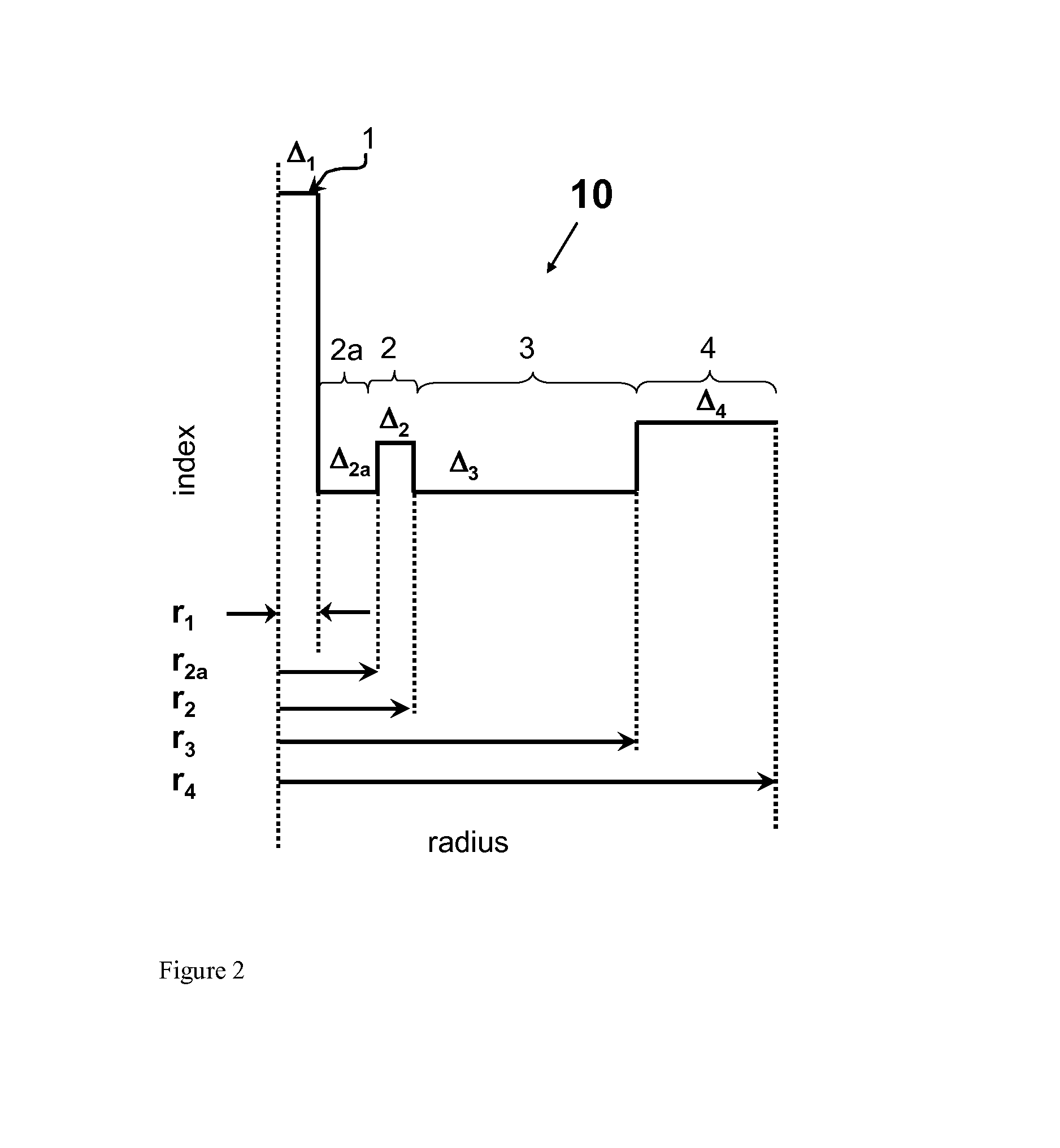
[0055]Table 2 below list characteristics of illustrative examplary embodiments 24-25 with relative refractive index profile similar to that shown in FIG. 2. Optical fibers of FIG. 2 are similar to those of FIG. 1 in that that they have a trench (region 3) offset from the core (region 1) with the inner cladding region 2 situated there between. However, in FIG. 2 embodiments the fibers also comprise region 2A situated directly adjacent to the core and sandwiched between the core (region 1) and the inner cladding region 2. More specifically, FIG. 2 shows illustrates the refractive index profile that has 5 segments: a central core (region 1) and four surrounding cladding layers (inner cladding layers 2A, 2 and 3 and an outer cladding 4 that in these embodiments with the refractive index delta Δ4 (i.e., the overclad). The core can have a step index or an alpha profile. The first layer surrounding the core can have a flat index or an alpha profile. The relative refract...


PUM


Abstract

An optical fiber comprising: (I) a germania doped central core region having outer radius r1 and (II) a maximum relative refractive index Δ1max and a cladding region including (i) a first inner cladding region having an outer radius r2>5 microns and refractive index Δ2; (ii) a and a second inner cladding region having an outer radius r3>9 microns and comprising refractive index Δ3; and (iii) an outer cladding region surrounding the inner cladding region and comprising refractive index Δ4, wherein Δ1max4, Δ23, and wherein 0.01%≦Δ4−Δ3≦0.09%, said fiber exhibits a 22 m cable cutoff less than or equal to 1260 nm, and 0.25≦r1/r2≦0.85.

Description

CROSS-REFERENCE TO RELATED APPLICATIONS[0001]This application claims the benefit of priority under 35 U.S.C. §119 of U.S. Provisional Application Ser. No. 61 / 564,455 filed on Nov. 29, 2011 the content of which is relied upon and incorporated herein by reference in its entirety.BACKGROUND[0002]1. Field[0003]The disclosure relates generally to optical fibers having low bend losses.[0004]2. Technical Background[0005]There is a need for low bend loss optical fibers, particularly for optical fibers utilized in so-called “access” and fiber to the premises (FTTx) optical networks. Optical fiber can be deployed in such networks in a manner which induces bend losses in optical signals transmitted through the optical fiber. Some applications that can impose physical demands, such as tight bend radii, compression of optical fiber, etc., that induce bend losses include the deployment of optical fiber in optical drop cable assemblies, distribution cables with Factory Installed Termination System...

Claims


Application Information

Patent Timeline
IPC IPC(8): G02B6/028
CPCG02B6/028G02B6/02395G02B6/03666G02B6/0365G02B6/0281
Inventor BOOKBINDER, DANA CRAIGLI, MING-JUNTANDON, PUSHKARWEST, JAMES ANDREW
Owner CORNING INC
Why Eureka
Try Eureka