

Motor stator
- Summary
- Abstract
- Description
- Claims
- Application Information
AI Technical Summary
Benefits of technology
Problems solved by technology
Method used
Image

Examples
first embodiment
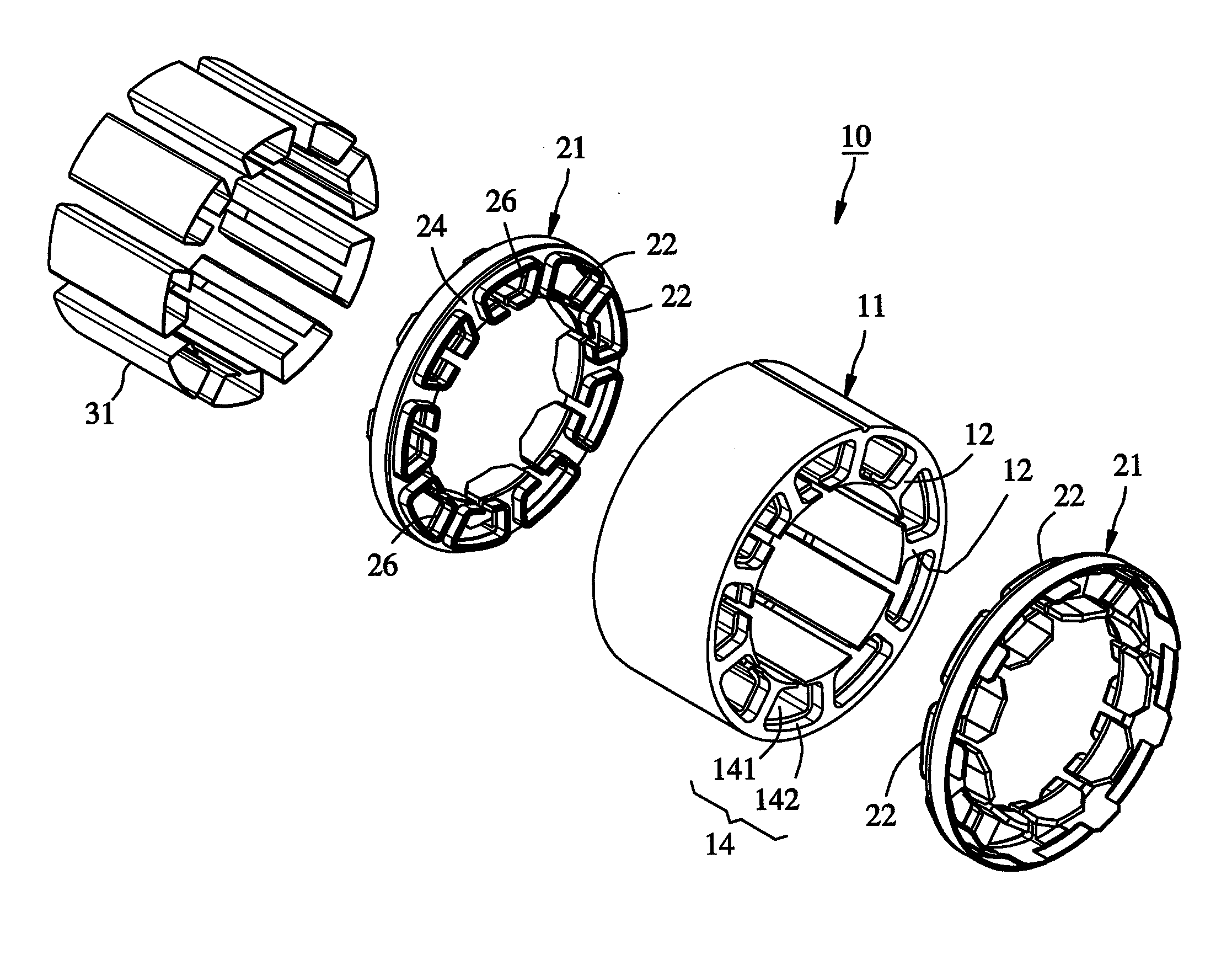
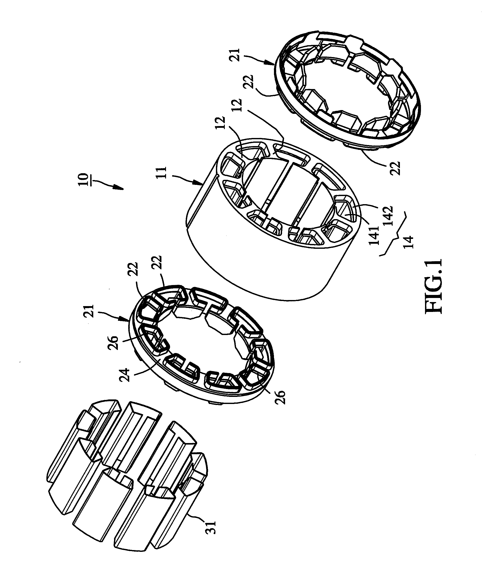
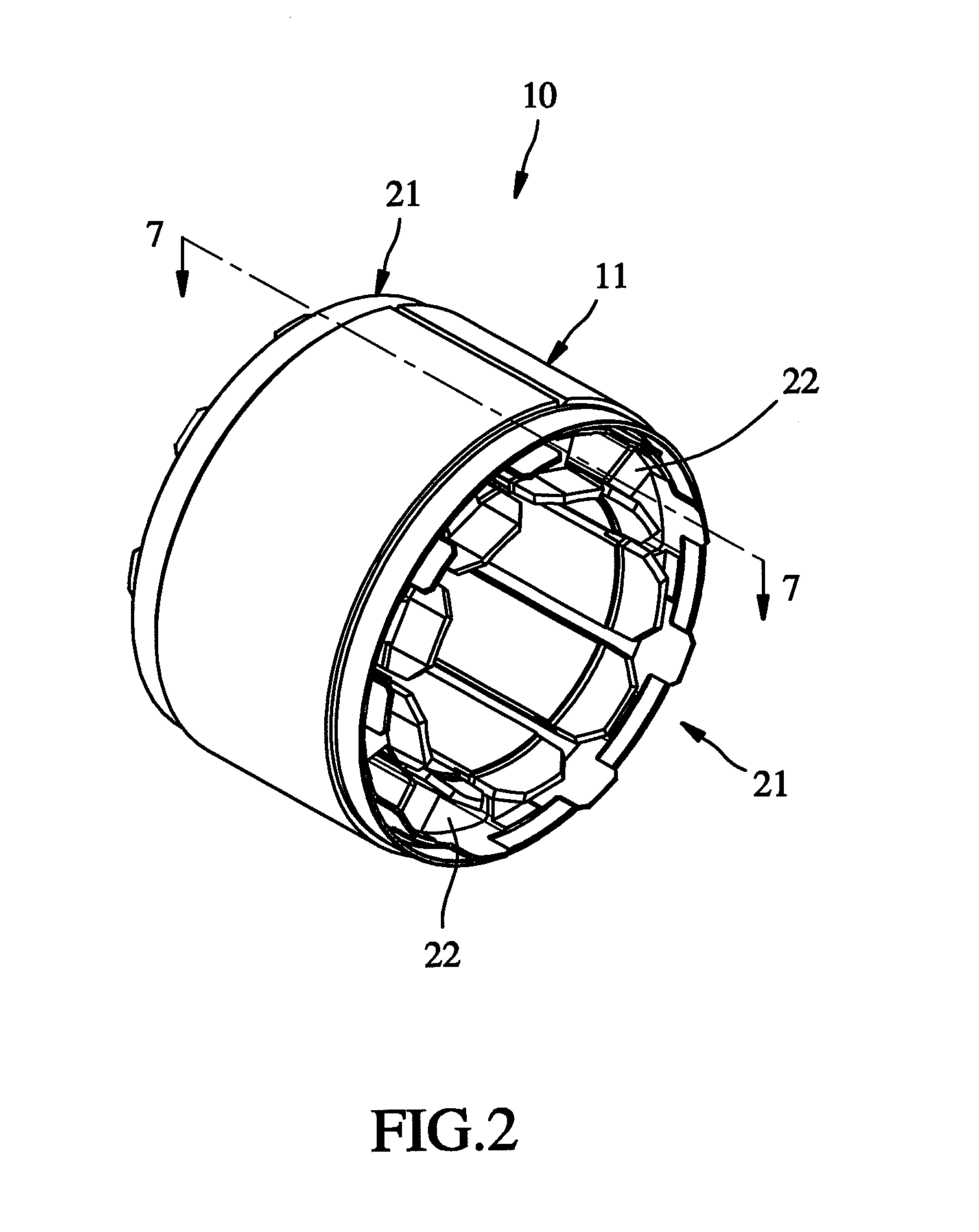
[0029]Referring to FIGS. 1 through 8, a motor stator 10 in accordance with the present invention is shown. The motor stator 10 comprises a body member 11, two wire racks 21, and a plurality of insulation sheets 31.
[0030]The body member 11 is formed of a stack of silicon steel plates. To avoid a blurred vision due to too many lines in the drawing, the body member 11 is illustrated in a block but not in a stack of silicon steel plates. The body member 11 comprises a plurality of inwardly extending polar columns 12, and a wire-winding groove 14 defined between each two adjacent polar columns 12. Further, the body member 11 defines in the axial direction thereof a middle section 111 and two opposing end sections 112 at the two ends of the middle section 111. The middle section 111 has a predetermined height. The end sections 112 have a predetermined height. The diameter of the end wire-winding groove sections 142 of the wire-winding grooves 14 corresponding to the end section portions 1...
second embodiment
[0041]Subject to the characteristic that the wall thickness of the foot tubes 51 reduces gradually in direction toward the distal end, the insulation sheets 61 can easily be inserted into the end wire-winding groove sections 442 of the wire-winding grooves 44 corresponding to the end section portions 412 of the body member 41 and respectively stopped between the stop flanges of the two wire racks. Thus, this second embodiment facilitates rapid installation.
[0042]Other structural features and effects of this second embodiment are as same as the aforesaid first embodiment, and therefore, it is not necessary to go into details.
[0043]Further, it is to be understood that, in the aforesaid two embodiments, the length of the foot tubes 22 can be shorter than the height of the end section portions 112 of the body member 11, as shown in FIG. 12. Thus, the wire racks 21 have their abutment faces 24 respectively abutted against the outer surfaces of the respective end section portions 112 of t...
PUM
 Abstract
Description
Claims
Application Information