
Vehicle headlight module mounted on sliders, corresponding support and headlight

a technology for vehicle headlights and sliders, which is applied in vehicle headlights, transportation and packaging, lighting and heating devices, etc., can solve the problems of low experience of long-term durability of leds in these operating conditions, defects risk, and inability to be removed or replaced, so as to reduce costs and reduce the quality of lighting and/or signaling beams.

Active Publication Date: 2013-06-06
VALEO VISION SA
View PDF3 Cites 4 Cited by
  • Summary
  • Abstract
  • Description
  • Claims
  • Application Information

AI Technical Summary

Benefits of technology

The invention allows for easy replacement of light sources without affecting the lighting or signaling beam. The device is designed to allow for the replacement of essential optical elements in the lighting and / or signaling device. This facilitates the use of new LED models that may be more efficient and up-to-date, providing a standardization of the LEDs and reducing costs. The invention helps to dispose of obsolete LED models and provide replacement modules with new LED technology.

Problems solved by technology

These operating conditions are generally controlled so that the LEDs installed in the vehicle headlights and signaling devices retain a lifetime that is in principle greater than the lifetime of the vehicle and are consequently generally not removable or replaceable.
Given the recent nature of the use of LEDs for vehicle lighting and / or signaling, there is as yet very little experience as to long-term durability of these LEDs in these operating conditions.
Many opinions agree that defects risk appearing with time and that LED replacements may prove necessary.
The replacement of one or more light sources of a lighting and / or signaling module, in particular of a headlight, is, however, a potential source of misalignment of the beam.
The solution proposed by this document consequently does not allow the user of the vehicle to replace the light source given that a meticulous adjustment will then be necessary.
This mounting is, however, essentially limited to the light sources of incandescent type.
The mounting provided in this teaching is difficult to apply to a light source of the LED type because of the bulk of these components.

Method used


Image

  • Vehicle headlight module mounted on sliders, corresponding support and headlight
  • Vehicle headlight module mounted on sliders, corresponding support and headlight
  • Vehicle headlight module mounted on sliders, corresponding support and headlight

Examples


Embodiment Construction

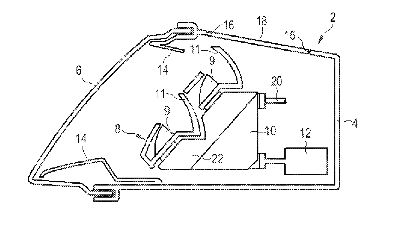
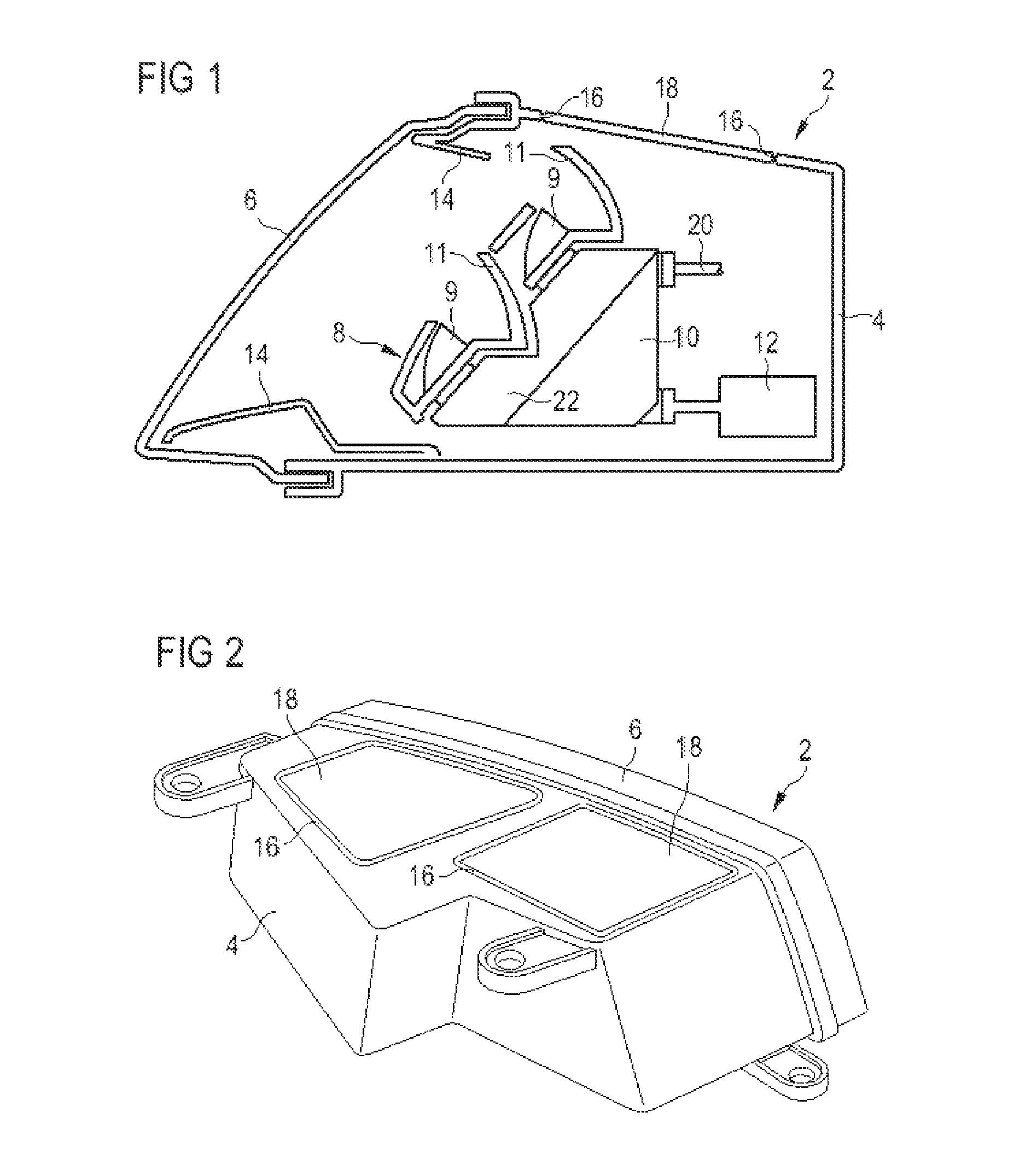
[0047]In the following description, an exemplary embodiment of the invention will be described in a fairly detailed manner. For reasons of convenience and clarity of the explanation, this example deals with a lighting device, that is to say a headlight and its corresponding lighting module usually situated at the front of the vehicle. It is, however, understood that the invention, and more particularly the technical solutions of the examples which follow, apply also to signaling modules, that is to say notably to modules for signaling lights usually situated at the rear of the vehicle.

[0048]In the following description, reference will be made to the optical axis of the lighting device. In this context, the use of the terms “front” and “rear” should be understood in relation to the direction of lighting of the modules. When the module is arranged at the front of the vehicle, the expression “front” will correspond with the normal direction of advance of the vehicle, whereas it will be...


PUM


Abstract

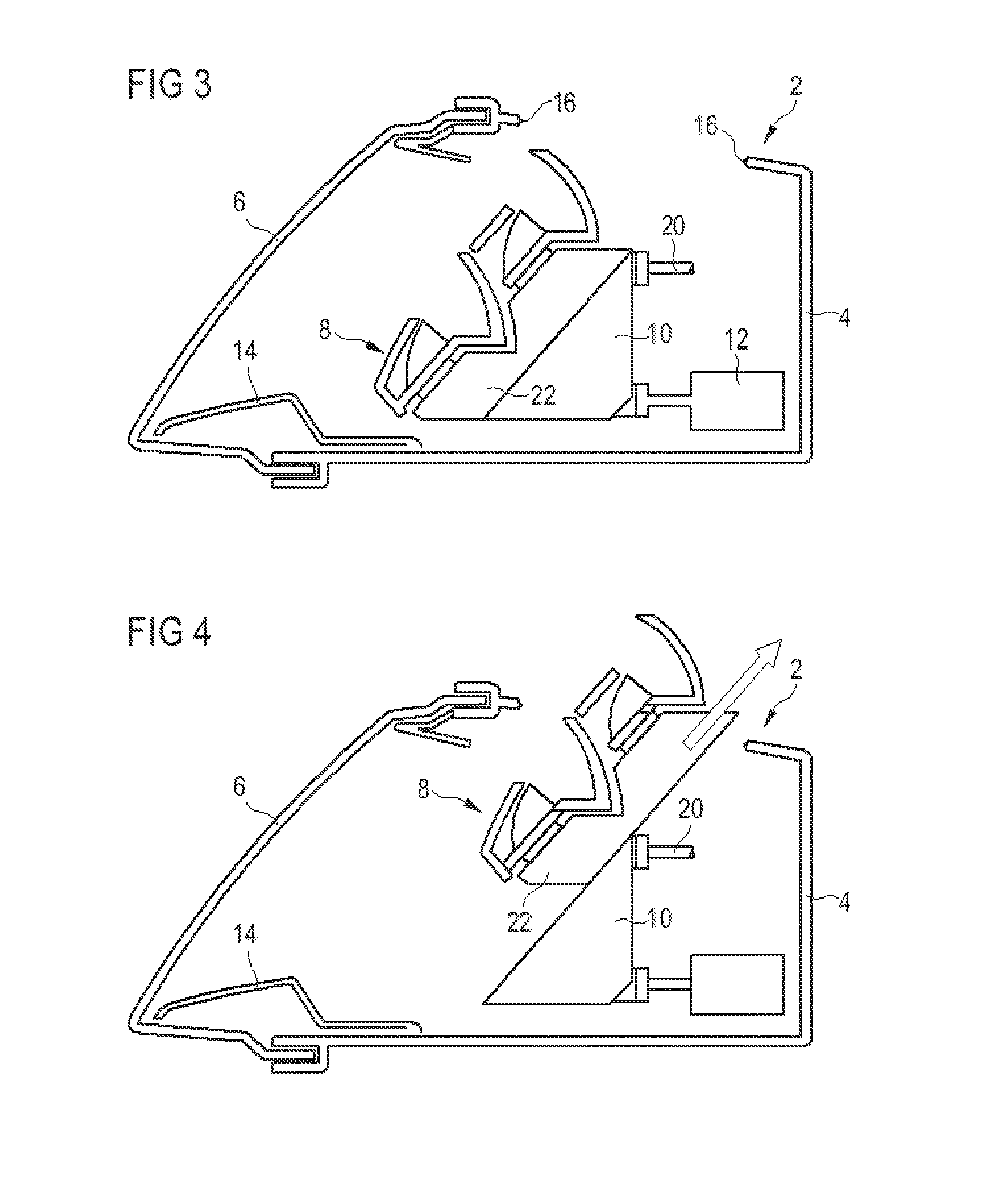
A vehicle headlight comprising at least one lighting module mounted on a support. The module comprises a base with a mounting surface inclined backward and toward the top of the headlight. The support comprises a corresponding mounting surface. Positioning means with sliders are provided on these surfaces so as to be able to extract the module and fit it by a translational movement in a direction contained within the plane of the mounting surfaces. The housing comprises a removable portion positioned in the extension of the module in the direction of translation of the positioning means with sliders. The wall of the housing comprises precuts on the circumference of the removable portion. This arrangement makes is possible to easily replace a bulky lighting module such as that of a headlight with style functions.

Description

CROSS-REFERENCE TO RELATED APPLICATIONS[0001]This application claims priority to French Application No. 1158612 filed Sep. 27, 2011, which application is incorporated herein by reference and made a part hereof.BACKGROUND OF THE INVENTION[0002]1. Field of the Invention[0003]The invention deals with a lighting and / or signaling module, notably for a vehicle. The invention also deals with a lighting and / or signaling module support as well as a lighting and / or signaling device comprising the module and / or the support.[0004]2. Description of the Related Art[0005]The use of light sources of the light-emitting diode (LED) type is becoming increasingly commonplace in motor vehicle headlights and signaling lights. The LEDs have a significantly longer lifetime than the incandescent lamps, namely a routine lifetime greater than 10 000 hours, even ranging up to 35 000 and even 50 000 hours, or significantly more than the lifetime of a motor vehicle. The lifetime of an LED is, however, linked to ...

Claims


Application Information

Patent Timeline
Patent Type & Authority Applications(United States)
IPC IPC(8): B60Q1/00F21V15/01F21V29/00
CPCB60Q1/0064F21V15/01B60Q1/007F21S48/321F21S48/1104F21S48/1305F21S48/1388B60Q1/2696F21S41/19F21S41/39F21S41/36F21S45/49F21S45/47F21S41/365
Inventor MOISY, ERICGARCIA, ISIDROAGUILAR DEL MORAL, JOSE-ANTONIOCABANNE, DAMIENCONTRELAS-LUQUE, ANTONIOLE BARS, JEAN-FRANCOIS
Owner VALEO VISION SA
Learn More