Reporting circuit breaker and system

Active Publication Date: 2013-06-06
ROHRBAUGH THOMAS M
View PDF2 Cites 120 Cited by
  • Summary
  • Abstract
  • Description
  • Claims
  • Application Information

AI Technical Summary

Benefits of technology

[0010]The circuit breaker may have conventional external configuration and dimensions. This enables the circuit breaker to be installed in conventional pre-existing distribution panels, in turn enabling the novel billing arrangement to be implemented even where a conventional electrical installation is present in a building. By having a circuit breaker with conventional external configuration and dimensions, but the added metering and signaling functionality disclosed herein, a user is able to simply: 1) remove the cover of a standard electrical panel; 2) remove the conventional non metering circuit breaker by popping it out of its location in the panel; and 3) snap in the new metering circuit breaker disclosed herein in the same space occupied by the old circuit breaker. The anticipated time of replacement is less than one minute and you have now gone from simply an over current protection device to an over current protection device and a current measuring device with no alteration to the electrical panel or electric circuit. There is virtually no cost to make this improvement except the cost of the novel circuit breaker disclosed herein and

Problems solved by technology

However, the power distribution procedures and apparatus imposed by others, such as to comply with the National Electric Code, require particular procedures and apparatus which may not be available or cost-effective for retrofitting a multi-tenant building.
However, periodic turnover of tenants and the resulting continual renovation and reallocation of building space to different tenants typically requires that any tenant undergoing a change, such as increasing or decreasing space within the building, or adding or deleting branch circuits to serve changing loads, may requiring re-routing of

Method used


Image

  • Reporting circuit breaker and system
  • Reporting circuit breaker and system
  • Reporting circuit breaker and system

Examples


Embodiment Construction

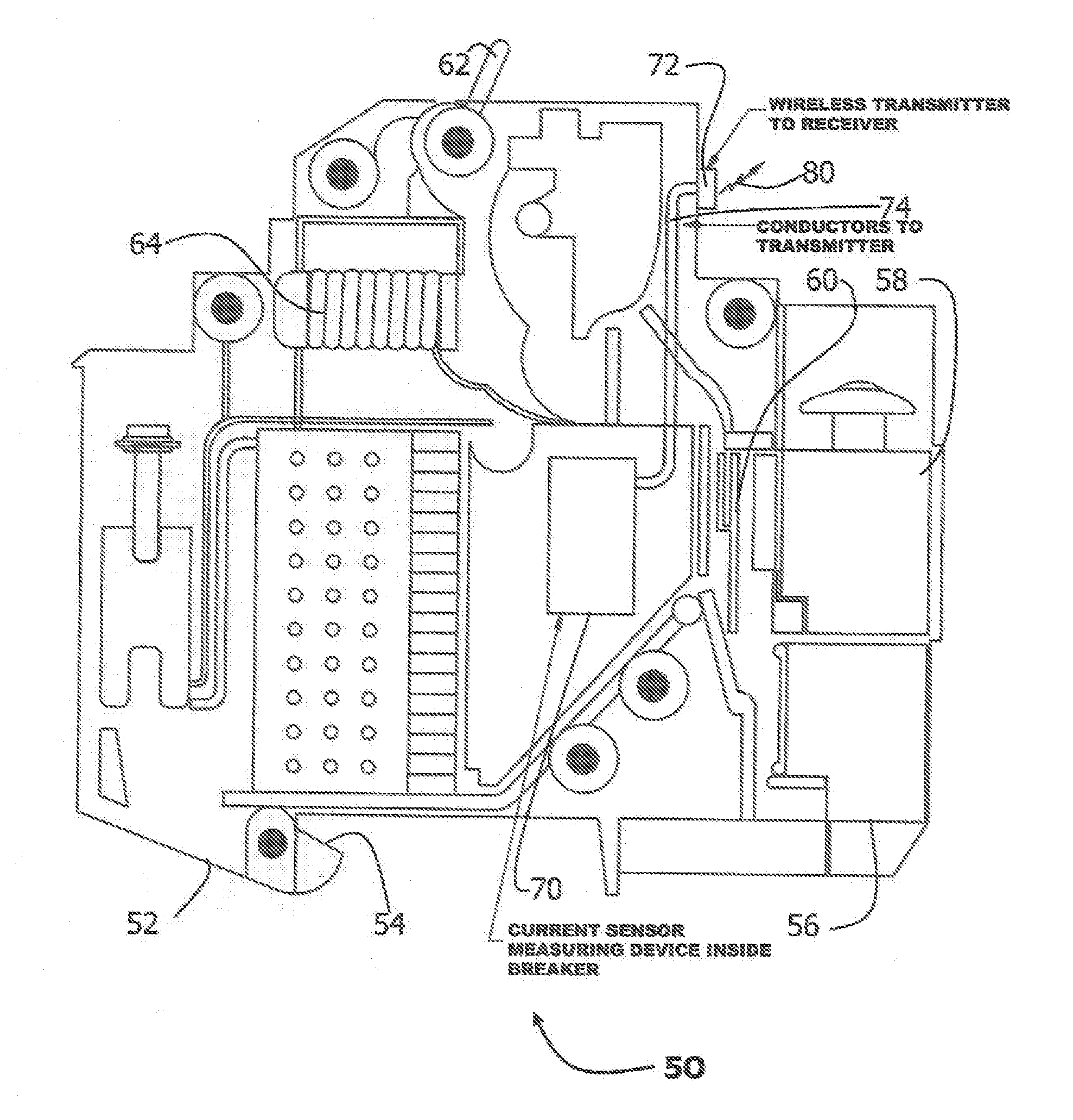
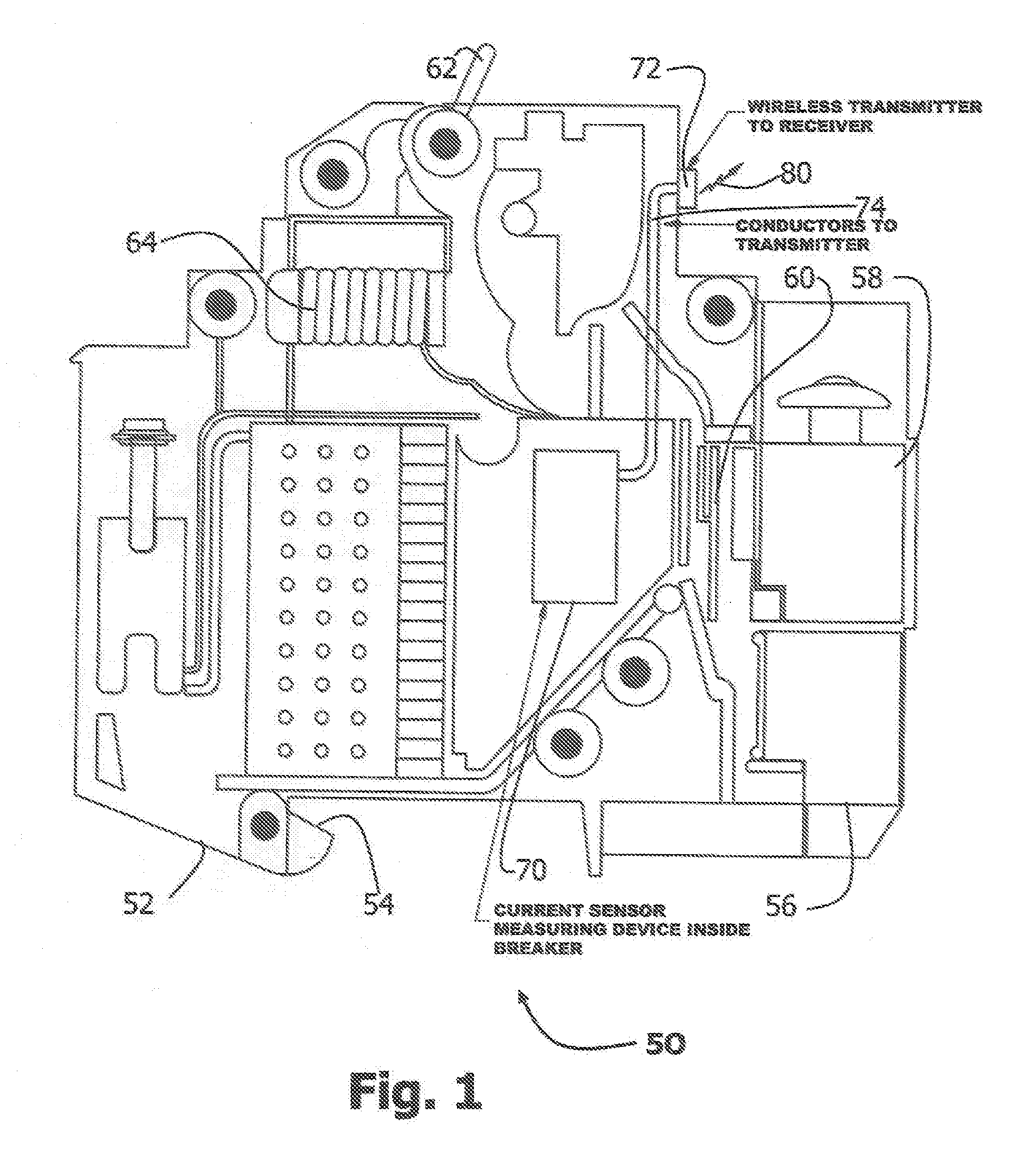
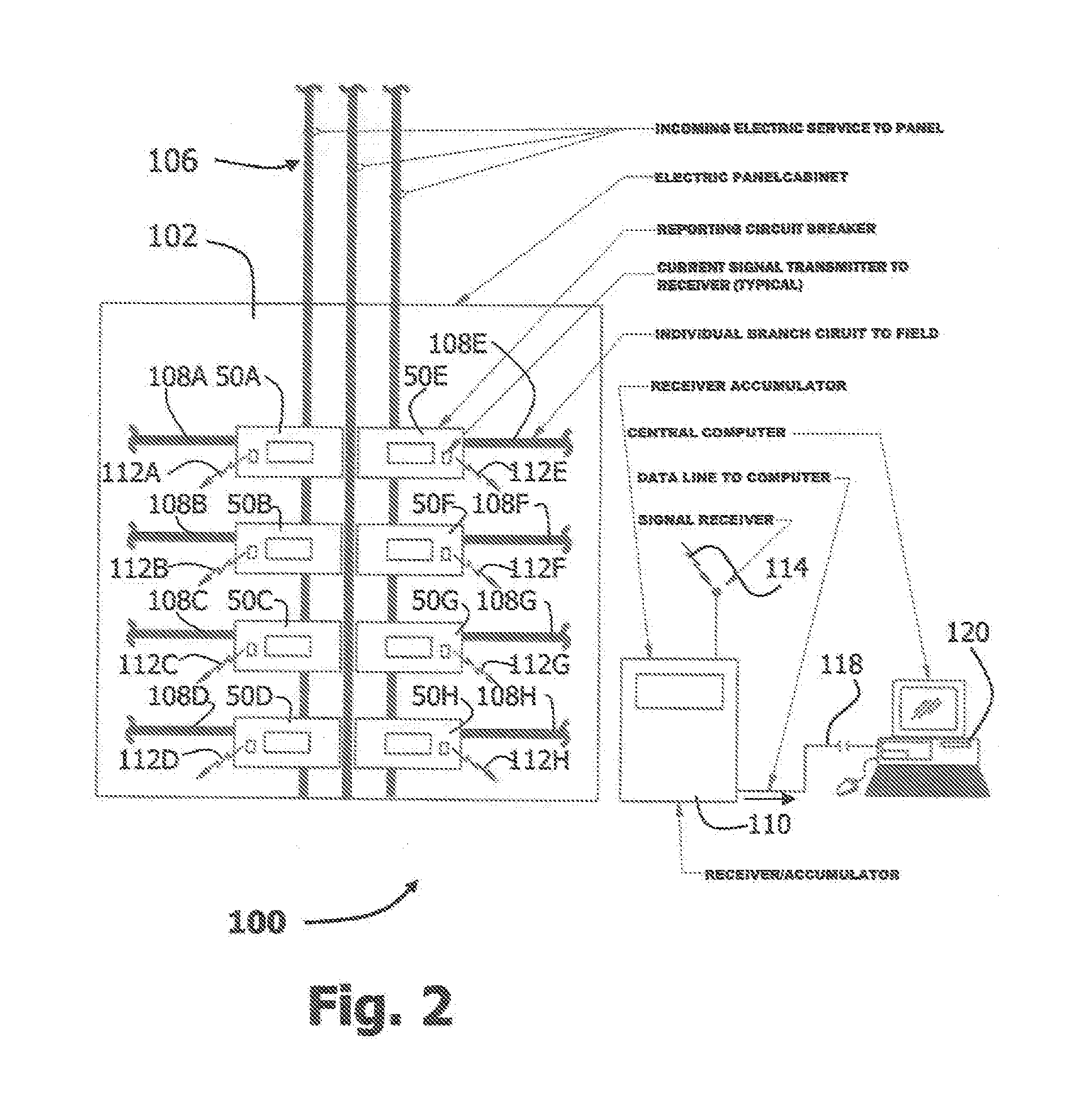
[0021]Referring first to FIG. 1, according to at least one aspect of the invention, there is shown a circuit breaker 50 of the type which engages a distribution panel such as the distribution panel 102 (see FIG. 2) by a protrusion 42. The distribution panel 102 may be of a conventional type, such as being of the QO™ or Homeline™ series, these being commercial products of the Square D.Company of Palatine, Ill. Similar products are offered by established manufacturers such as General Electric, Westinghouse, Allen Bradley, and Cutler Hammer, to name but a few. Circuit breakers which may be used with the distribution panels are individually available on the commercial market in the United States. These may be called plug-in circuit breakers since they are installed in the distribution panel into their final operative position by a snap fit of sorts, or resilient engagement, without using fasteners such as screws. The circuit breaker 50 may in many respects be similar to conventional cir...


PUM


Abstract

A circuit breaker having internal power monitoring and data signal generating apparatus, and a system for utilizing such a circuit breaker in a facility having a plurality of tenants served by branch circuits from a plurality of distribution panels. The circuit breaker radiates signals indicative of power consumption of the branch circuit protected thereby, together with a unique address identifier tied to one tenant. Electrical billings are based on summing all signals for each tenant. Changes to branch circuits during tenancy will not disturb correct billings since individual circuit breakers are associated with that tenant using power supplied by each branch circuit. Hence changes to branch circuits may be limited to modify building space locations served by the modified branch circuit, and need not be further modified to maintain correct billing in light of the circuit changes.

Description

CROSS-REFERENCE TO RELATED APPLICATION[0001]This application claims priority to U.S. Non-Provisional Utility application Ser. No. 12 / 418,182 filed Apr. 3, 2009, the contents of which are incorporated by this reference.FIELD OF THE INVENTION[0002]The present invention relates to electrical power distribution systems for facilities such as commercial buildings housing plural tenants, and more particularly, to circuit protective systems which have the ability to communicate data pertaining to electrical system operation back to a central station in a manner enabling electrical consumption billings for the tenants to remain appropriate despite periodic reallocation of branch circuits to different tenants.BACKGROUND OF THE INVENTION[0003]Increasing demand for conservation of resources and accounting for the particular use of those resources, specifically electricity, encourages building owners of buildings containing plural entities such as tenants to retrofit buildings with associated m...

Claims


Application Information

Patent Timeline
IPC IPC(8): G06Q30/00G08B21/00G01R19/00
CPCG06Q10/06G06Q30/04G06Q50/06H01H71/04G06Q20/102H01H9/168
Inventor ROHRBAUGH, THOMAS M.
Owner ROHRBAUGH THOMAS M
Why Eureka
Try Eureka