Visual editor for defining geo fence boundaries

a technology of geo fences and visual editors, applied in the field of workflow systems, can solve problems such as unfavorable users and inability to easily find solutions

Active Publication Date: 2013-06-06
ADOBE SYST INC
View PDF7 Cites 4 Cited by
  • Summary
  • Abstract
  • Description
  • Claims
  • Application Information

AI Technical Summary

Problems solved by technology

Such solutions are not user friendly as a user typically cannot easily correlate an event and / or an action with a geographic location by entering spatial coordinates into traditional form fields.

Method used


Image

  • Visual editor for defining geo fence boundaries
  • Visual editor for defining geo fence boundaries
  • Visual editor for defining geo fence boundaries

Examples


Embodiment Construction

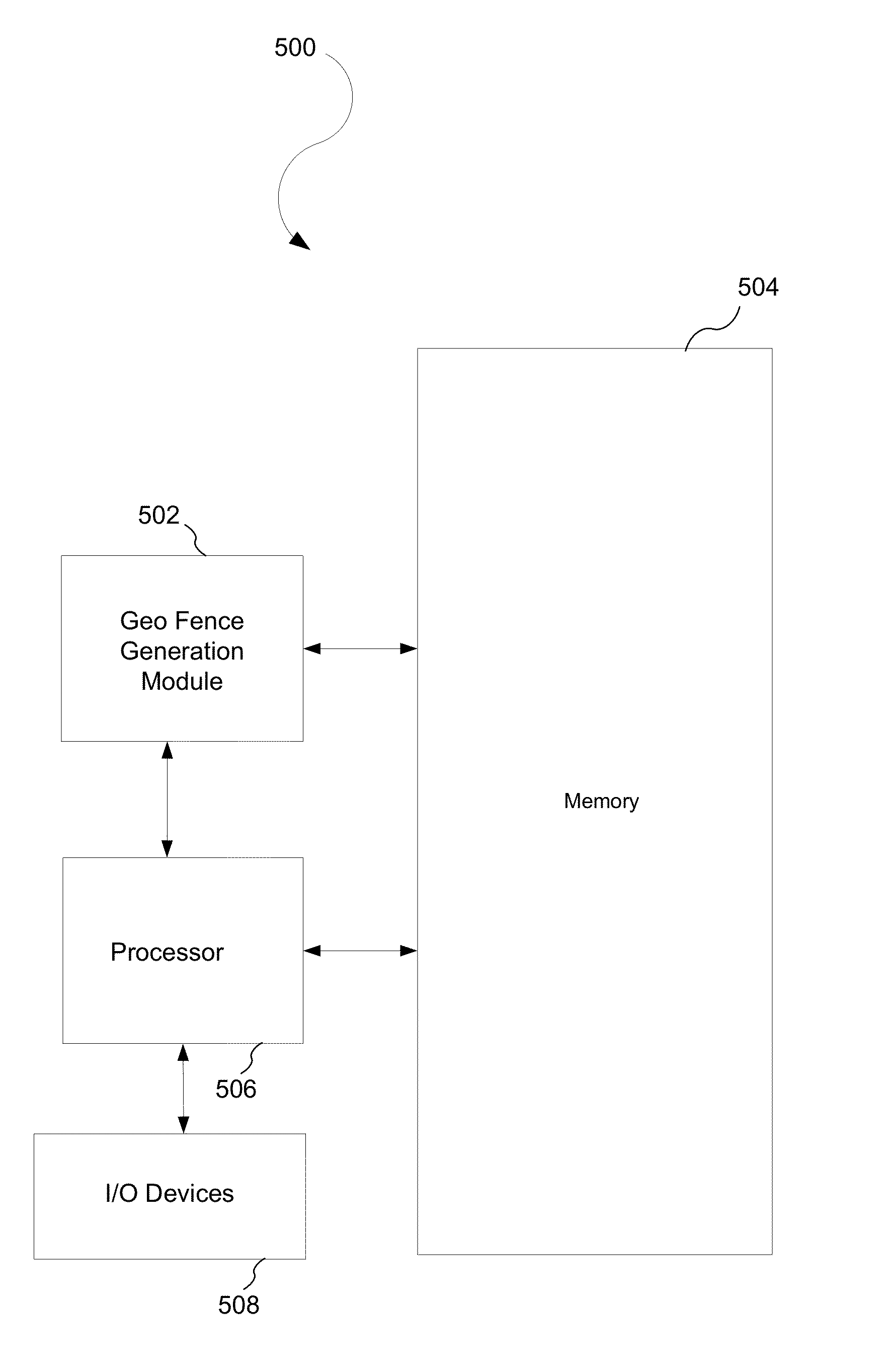
[0016]A visual editor may be utilized in conjunction with a workflow authoring program. The visual editor may be utilized to define boundaries of a geo fence, which is a user-defined zone that is represented by a shape. An example of a shape is a polygon where each point represents a coordinate on a map to define a space with boundaries. A geo fence may be event-based to trigger rules and / or events. For example, a geo fence may trigger server-side business rules and / or client-side events. In one embodiment, the coordinates of a geo fence are Global Positioning System (“GPS”) based. GPS is a space-based global navigation satellite system (“GNSS”) and provides location and time information. In another embodiment, the coordinates of a geo fence may be Real-time Locating System (“RTLS”) based. RTLS is a type of local positioning system that allows tracking and identification of the location of objects in real-time. For example, badges or tags may be attached to the objects and readers m...


PUM


Abstract

A workflow authoring program generates a workflow. Further, a visual editor is invoked. In addition, a portion of a map is selected with the visual editor by marking a geo fence with boundaries that indicate the portion. The workflow authoring program also establishes a geo decision point in the workflow at which a determination is made if a condition is met within the geo fence.

Description

BACKGROUND[0001]1. Field[0002]This disclosure generally relates to workflow systems. More particularly, the disclosure relates to a visual editor that defines a workflow.[0003]2. General Background[0004]Workflow authoring systems typically allows users to author a workflow. The workflow may be utilized to provide a sequence of events in which tasks are to be performed. For example, a project may be assigned a workflow with particular tasks assigned to particular workers and resources at certain dates and times.[0005]Location-aware workflows may be based on geographic locations associated with a workflow. For example, a geographic location may be provided for a task in a workflow. However, current solutions require users to enter the spatial coordinates for geographic locations for a workflow into traditional form fields. Such solutions are not user friendly as a user typically cannot easily correlate an event and / or an action with a geographic location by entering spatial coordinate...

Claims


Application Information

Patent Timeline
Patent Type & Authority Applications(United States)
IPC IPC(8): G06F3/048
CPCG06F3/048G06Q10/0633G06Q10/08
Inventor YOUNG, STACY
Owner ADOBE SYST INC
Why Eureka
Try Eureka