Energy reclaiming system for electric forklift truck

a technology for electric forklifts and energy reclaiming systems, which is applied in the direction of rotary clutches, couplings, fluid couplings, etc., can solve the problems of reducing the speed of the electronic device, lowering the efficiency of energy reclaiming, and reducing the speed of the working machine of the secondary consumer

Active Publication Date: 2013-06-13
DOOSAN IND VEHICLE
View PDF6 Cites 8 Cited by
  • Summary
  • Abstract
  • Description
  • Claims
  • Application Information

AI Technical Summary

Benefits of technology

[0016]The present disclosure is contrived to solve the above-mentioned problems, and the object of the present disclosure is to provide an energy reclaiming system for an electric forklift truck which, if a return flow amount generated when a working machine (or fork carriage) is lowered is smaller than a flow amount consumed by a secondary consumer, reclaims the return flow amount to an oil tank as it is, and if the return flow amount generated when the working machine is lowered is larger than the flow amount consumed by the secondary consumer, supplies the return flow amount to a hydraulic pump / motor so that the return flow amount can be used to operate the secondary consumer or converts mechanical energy of the return flow amount into electric energy so that the converted electric energy can be reclaimed to a battery.
[0021]The energy reclaiming system may further include a check valve 8 installed in a downstream working fluid line of the hydraulic pump / motor 2 such that the return flow amount passing through one of the two positions of the two position valve 51 or 51a is guided to the hydraulic pump / motor 2 without being leaked to the oil tank 7.
[0024]The present disclosure provides an energy reclaiming unit to a working fluid return line so that, if a return flow amount generated when a working machine is lowered is smaller than a flow amount consumed by a secondary consumer, the return flow amount can be reclaimed to an oil tank, which prevents cavitations generated by a hydraulic pump / motor during an energy reclaiming process according to the related art or a dull operation of a secondary consumer.

Problems solved by technology

However, in the energy reclaiming system for an electric forklift truck according to the related art, it is necessary to limit a speed of the electronic device 1 to prevent cavitations generated when the suctioned flow amount is insufficient as compared with the flow amount discharged from the hydraulic pump / motor 2, in the case where the return flow amount generated when the working machine (or fork carriage) is lowered is smaller than the flow amount consumed by a secondary consumer (the tilt cylinder 4, the side shift cylinder 5 or the reach cylinder 6), which lowers energy reclaiming efficiency.
In addition, in the energy reclaiming system for an electric forklift truck according to the related art, when the working machine (fork carriage) is lowered and the secondary consumer is operated at the same time, it is inevitably necessary to limit the speed of the electronic device 1 to prevent cavitations generated when the suctioned flow amount is insufficient as compared with the flow amount discharged from the hydraulic pump / motor 2, which lowers the speed of the working machine of the secondary consumer.

Method used


Image

  • Energy reclaiming system for electric forklift truck
  • Energy reclaiming system for electric forklift truck
  • Energy reclaiming system for electric forklift truck

Examples


Embodiment Construction

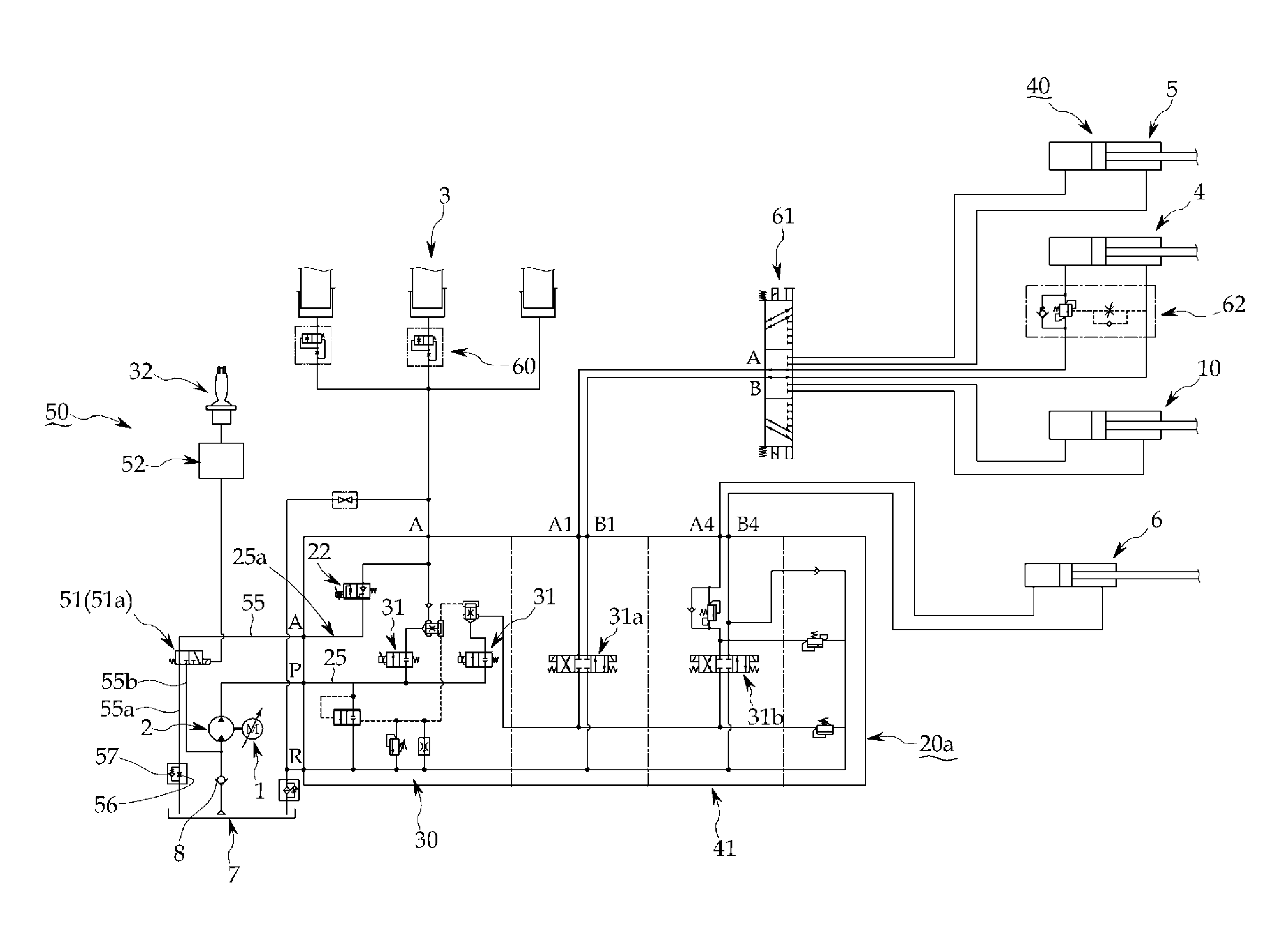
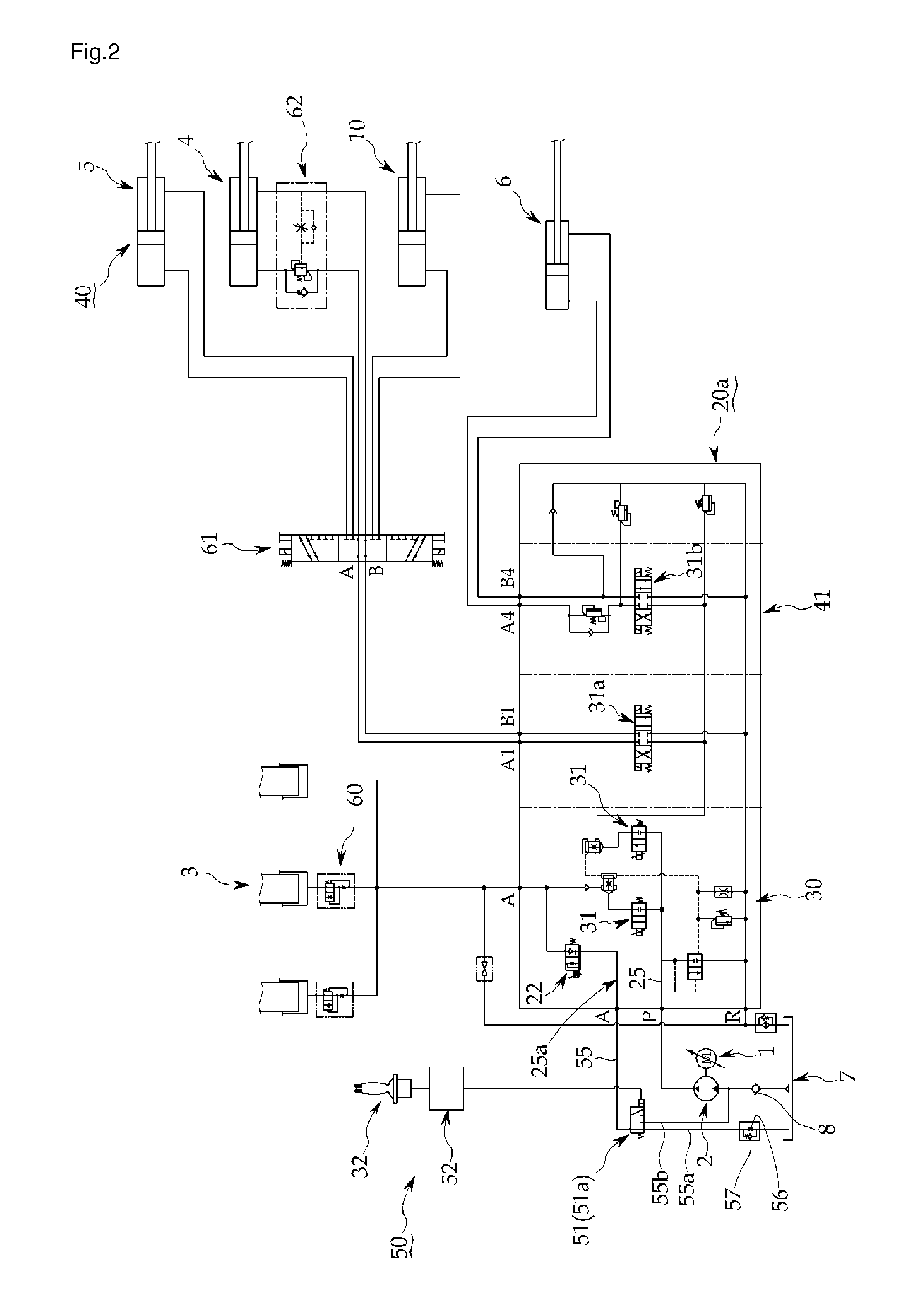
[0029]Hereinafter, an exemplary embodiment of an energy reclaiming system for an electric forklift truck according to the present disclosure will be described with reference to FIGS. 2 and 3.

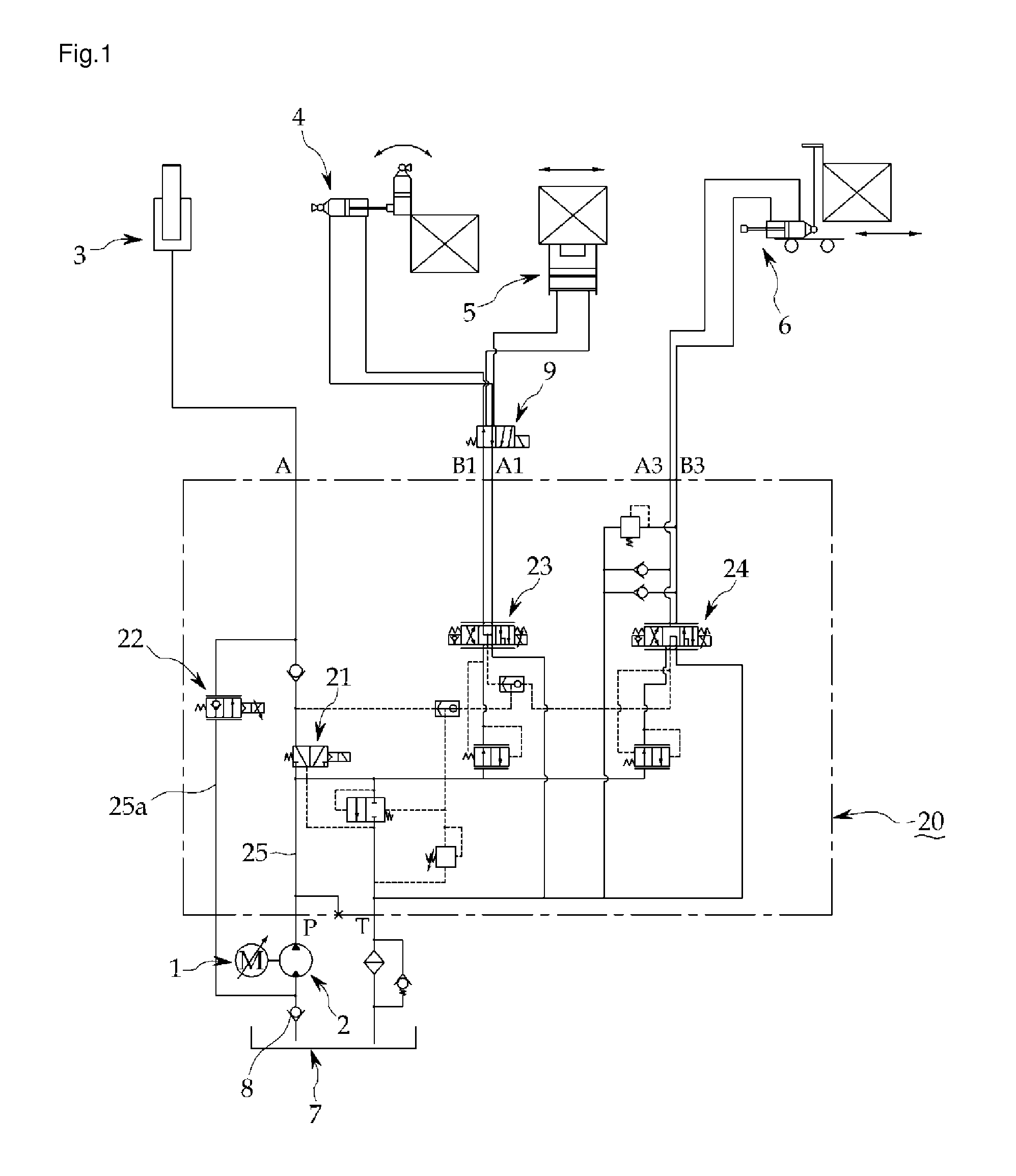
[0030]FIG. 2 is a hydraulic circuit diagram illustrating an energy reclaiming system for an electric forklift truck according to the present disclosure in a state where a two position valve is converted into a first position for opening a working fluid return line to an oil tank. FIG. 3 is a hydraulic circuit diagram illustrating the energy reclaiming system for an electric forklift truck according to the present disclosure in a state where the two position valve is converted into a second position for opening the working fluid return line to a hydraulic pump / motor.

[0031]The energy reclaiming system for an electric forklift truck according to the present disclosure includes an electronic device 1, a hydraulic pump / motor 2 connected to the electronic device 1 and configured to perform two functio...


PUM


Abstract

The present disclosure relates to an energy reclaiming system for an electric forklift truck. The energy reclaiming system includes an electronic device operated by a motor when a working machine is raised and operated by a generator when the working machine is lowered, a hydraulic pump / motor connected to the electronic device and configured to perform two functions of a hydraulic pump and a hydraulic motor, a main control valve unit including a lift cylinder operating unit connected to the hydraulic pump / motor and configured to operate a lift cylinder and a secondary consumer operating unit connected to the hydraulic pump / motor and configured to operate a secondary consumer, and a control lever including a control valve configured to control the lift cylinder or the secondary consumer through the lift cylinder operating unit and the secondary consumer operating unit of the main control valve unit, respectively. The energy reclaiming system includes: a working fluid return line provided with a flow amount limiting valve configured to interrupt a flow of a return flow amount generated by the lift cylinder when the working machine (or fork carriage) is lowered; and an energy reclaiming unit installed in the working fluid return line and configured to, if a return flow amount generated when the working machine is lowered is smaller than a flow amount consumed by the secondary consumer, reclaim the return flow amount to an oil tank, and, if the return flow amount generated when the working machine is lowered is larger than the flow amount consumed by the secondary consumer, guide the return flow amount to the hydraulic pump / motor.

Description

[0001]This Application is a Section 371 National Stage Application of International Application No. PCT / KR2011 / 003697, filed May 19, 2011 and published, not in English, as WO2011 / 145891 on Nov. 24, 2011.FIELD OF THE DISCLOSURE[0002]The present disclosure relates to an energy reclaiming system for an electric forklift truck, and more particularly, to an energy reclaiming system for an electric forklift truck which, if a return flow amount generated when a working machine (or fork carriage) is lowered is smaller than a flow amount consumed by a secondary consumer, reclaims the return flow amount to an oil tank as it is, and if the return flow amount generated when the working machine is lowered is larger than the flow amount consumed by the secondary consumer, reclaims energy of the return flow amount.BACKGROUND OF THE DISCLOSURE[0003]In general, forklift trucks are used to raise or lower freight or carry freight to a desired location within a restricted space, and are largely classif...

Claims


Application Information

Patent Timeline
Patent Type & Authority Applications(United States)
IPC IPC(8): B66F9/22
CPCB60L1/20B66F9/22B60L2200/42
Inventor HAN, DONG HOJANG, DAL SIK
Owner DOOSAN IND VEHICLE
Why Eureka
Try Eureka