Extendable frame work vehicle

a technology of extension frame and work vehicle, which is applied in the direction of tractors, instruments, navigation instruments, etc., can solve the problems of difficult and costly acquisition and transportation of such a variety of equipment, difficult and costly mastering of the many steering and control systems of these different vehicles, and difficult safety considerations, so as to improve safety and efficiency, enhance versatility, and safely allow greater lifting load capacities

Active Publication Date: 2009-02-12
EXTENDQUIP LLC
View PDF16 Cites 62 Cited by
  • Summary
  • Abstract
  • Description
  • Claims
  • Application Information

AI Technical Summary

Benefits of technology

[0010]The present invention provides extendable frame work vehicles offering enhanced versatility, safety and effectiveness. The vehicles include an adjustable wheelbase, a plurality of steering modes, and independently driven wheels. The work vehicles also have variable weight distribution system which can be employed to compensate for different weights lifted by the vehicle to different heights and angles dictated by a variety of work attached implements and terrain conditions. Finally, an electro-hydraulic system is provided including a sensor-responsive microprocessor controller, a plurality of sensors, at least one hydraulic pump, at least one hydraulic drive motor, and a valve network. The electro-hydraulic system enables variable extension and retraction of the wheelbase, drive and, steering of the wheels in various modes, and use of a variety of frontward and rearward attachments, all with an eye toward improved safety.
[0011]The invention further contemplates a variety of work vehicle embodiments and vehicle and attached implement combinations which are able to safely allow greater lift load capacities and offer safe operation in terrain conditions involving slopes and other undesirable variations. Embodiments include those equipped with adjustable boom arms, GPS systems with attachments for monitoring and determining work locations.

Problems solved by technology

Acquiring and transporting such a variety of equipment can be difficult and costly.
Further, mastering operation of the many steering and control systems for these different vehicles is known to be an arduous task.
Despite the many advantages offered by these vehicles, they also have limitations because of configuration or design.
There are also problematic safety considerations.
For example, when a skid steer vehicle lifts an item with a boom, bucket, or other attachment, the size of the load that can be safely moved may be compromised by the relatively short wheelbase of the conventional skid steer vehicle.
The short wheelbase often does not provide a sufficiently stable structure or counterweight to prevent tipping or other unwanted movement.
Similarly, traversing steep terrain in a vehicle with such a short wheelbase, particularly when carrying a load, can present problems.
Although various trucks and vehicles with wider wheelbases have been used for various tasks in the past, these vehicles generally have greatly diminished maneuverability and agility of operation.
However, these vehicles generally have a longer steering radius than a skid steer and are less maneuverable.
This limits the usefulness of such machines.
Traditional skid steer steering systems also have drawbacks related to the wear and tear they can cause on a work site.
Standard operation may cause the vehicle wheels to dig into the ground, particularly if the ground is soft turf.
For example, operators of work vehicles of the class are known to attempt to traverse inclines which may be too steep, lift loads that may be too heavy for the circumstances, drive vehicles with unfamiliar controls that are hard to manage, or operate in areas where visibility is limited or impaired and may contribute to a situation that is unsafe.
Generally, current designs are not able to cope with these hazards and most present work vehicles provide little ability to adapt or adjust the vehicle to address such dangers.
For example, if a front end loader were to become unstable because a load lifted was too heavy, an operator would have little choice but to rely on his or her quick reflexes to rapidly release the load to prevent the vehicle from tipping.

Method used


Image

  • Extendable frame work vehicle
  • Extendable frame work vehicle
  • Extendable frame work vehicle

Examples


Embodiment Construction

[0081]The present invention can be readily understood from the aforementioned figures, the following detailed description and certain embodiments of the present invention. It will be appreciated that the detailed embodiments are meant only as examples and are not intended to limit the scope of the concepts in any manner.

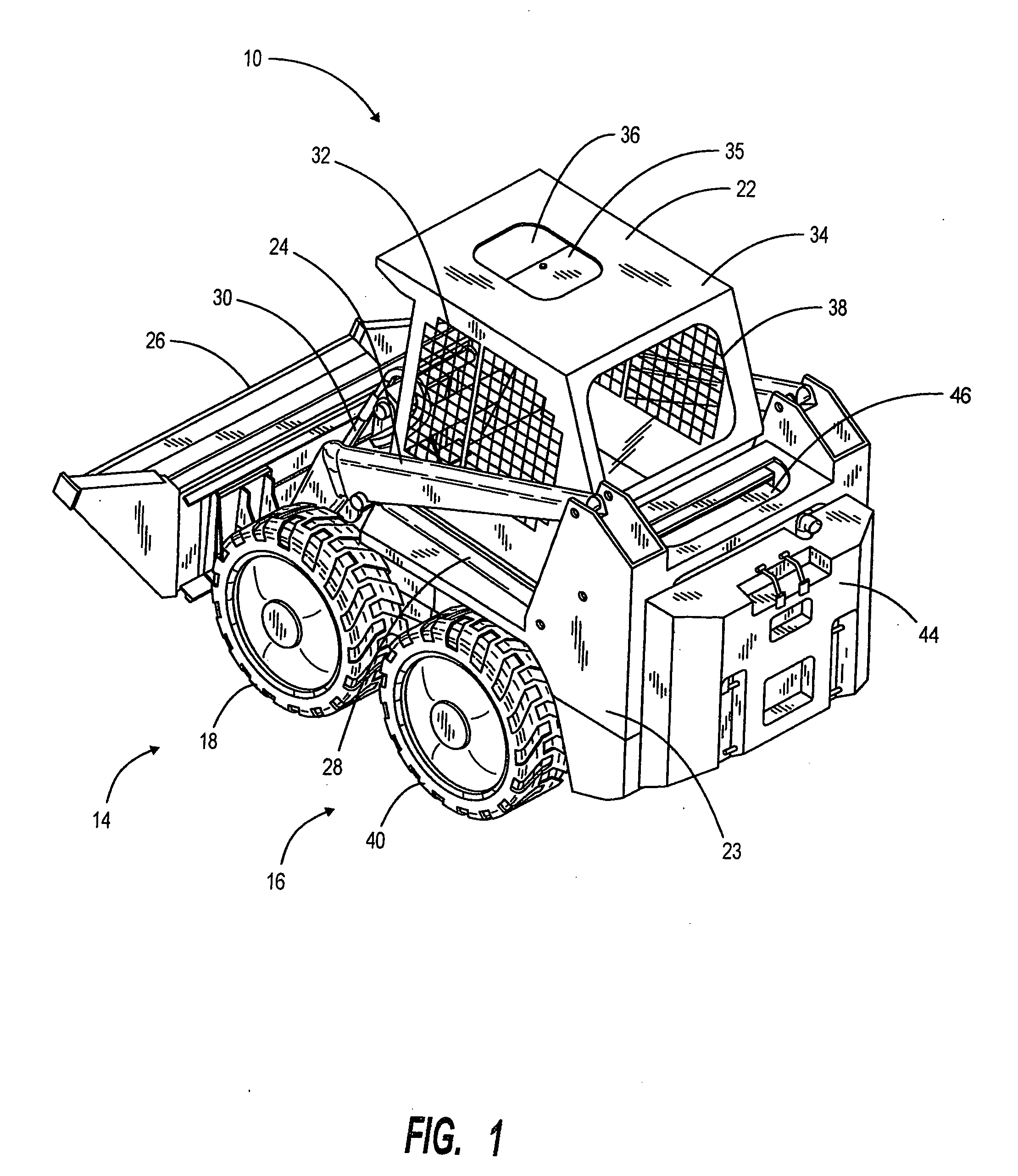
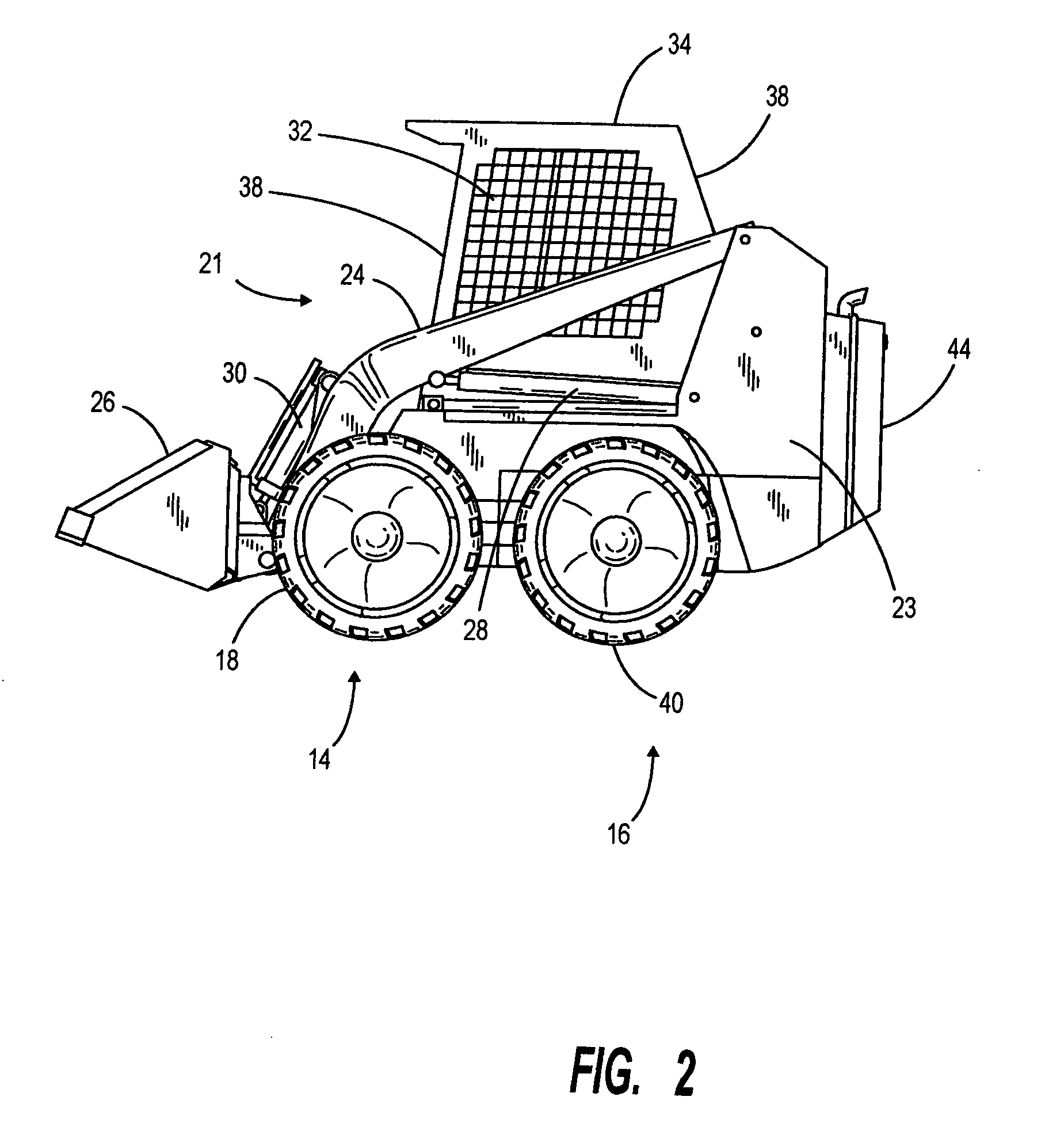
[0082]FIG. 1 sets forth the basic assembly of the work vehicle in its retracted configuration. In general, the overall appearance of the vehicle may resemble a typical skid steer design when in a retracted state. Although many of the vehicle's features are concealed in this contracted disposition, some of the work vehicle's basic structure can be appreciated from the perspective view of FIG. 1 and the side view of FIG. 2.

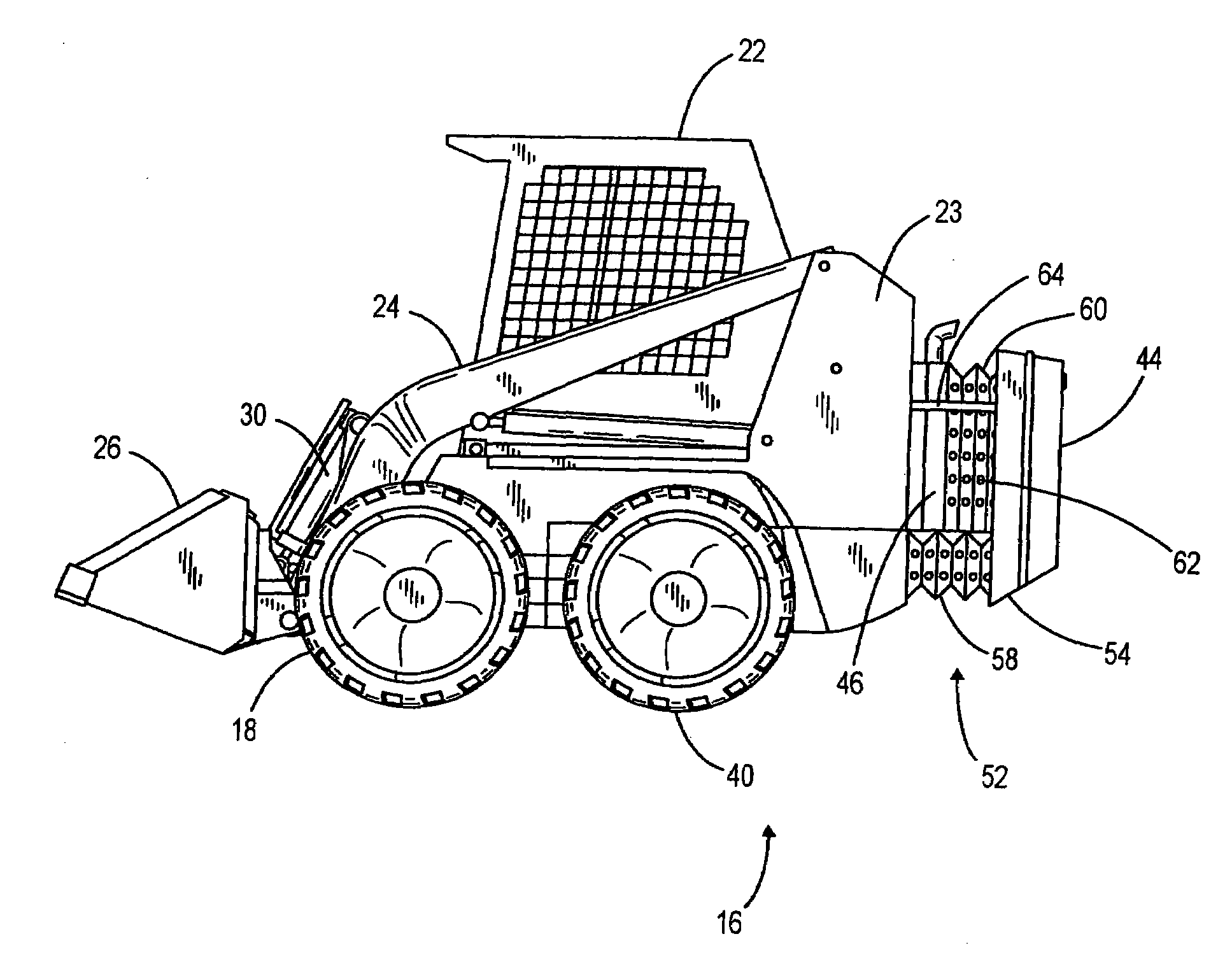
[0083]The work vehicle 10 generally, as will become apparent, includes a frame having a front portion 14 and a rear portion 16. Front portion 14 of the frame supports a lift arm assembly 21 (FIG. 2), an operator's cab 22, side housing members 23, and...


PUM


Abstract

An extendable frame work vehicle offering enhanced versatility, safety and effectiveness. The vehicle includes an adjustable frame with front and rear portions that extend or retract with respect to each other. The front portion is supported by a first pair of wheels and said rear portion is supported by a second pair of wheels. Each wheel is independently driven and steered. The vehicle also includes an engine mounted on the rear portion of the frame. Incorporated into the vehicle is an electro-hydraulic assembly which enables extension and retraction of the adjustable frame. The assembly includes a sensor-responsive microprocessor controller, at least one hydraulic pump, at least one hydraulic drive motor, and at least one valve network.

Description

BACKGROUND OF THE INVENTION[0001]I. Field of the Invention[0002]This invention relates generally to extendable frame vehicles, and more particularly to extendable frame work vehicles capable of enhanced performance of a variety of construction, landscaping, residential, agriculture and industrial tasks.[0003]II. Related Art[0004]In recent decades, construction equipment capabilities have increased dramatically as have the variety of specialized machines and vehicles that are useful to persons performing jobs at various worksites. To complete many projects, a variety of such specialized vehicles must be delivered to a specific worksite on large trucks or trailers. These vehicles may include skid steer loaders, front end loaders, backhoes, rough terrain forklifts, or any of a large number of trucks and similar devices. Acquiring and transporting such a variety of equipment can be difficult and costly. Further, mastering operation of the many steering and control systems for these diff...

Claims


Application Information

Patent Timeline
Patent Type & Authority Applications(United States)
IPC IPC(8): E02F7/00G01C21/20
CPCB62D21/14B62D55/0655B62D49/0678B62D49/085B66F9/0655B66F11/044B66F17/003E02F3/3414E02F3/96E02F9/02E02F9/024E02F9/028E02F9/18E02F9/2004E02F9/225E02F9/2253B60K25/06B62D37/04
Inventor OSSWALD, CHRISOSSWALD, WALTER A.DACK, MARCUS F.BUELT, KENNETHPRICE, JR., THOMAS E.SEVERNS, ALANWIERSCHKE, JEFFREY A.RACZ, JOE A.BAUER, DAVID R.GASAL, JUSTIN D.
Owner EXTENDQUIP LLC
Why Eureka
Try Eureka