Hydraulic steering transaxle and hydraulic driving vehicle

a transaxle and steering technology, applied in the direction of fluid gearings, transportation and packaging, gearing, etc., can solve the problems of increasing the rotary speed, requiring many parts and units to be assembled and properly located, and limiting design limitations, etc., to achieve the effect of convenient assembly

Inactive Publication Date: 2005-03-31
KANZAKI KOKYUKOKI MFG
View PDF7 Cites 63 Cited by
  • Summary
  • Abstract
  • Description
  • Claims
  • Application Information

AI Technical Summary

Benefits of technology

[0011] A first object of the invention is to provide a hydraulic steering transaxle which is compact and can be easily assembled.

Problems solved by technology

A large middle space of the vehicle is necessary for arranging the center differential gear unit, and two front and rear propeller shafts for transmitting power of the center differential gear unit to the respective front and rear transaxles, thereby causing designing limitation.
However, such displacement of the front hydraulic motor causes increase of the rotary speed of the front hydraulic motor, thereby requiring increase of the deceleration ratio between the front hydraulic motor and the steerable front wheels so as to be balanced with the rotary speed of the unsteerable rear wheels.
Further, if a steering transaxle incorporating a variable displacement hydraulic motor, a deceleration gear train and a differential gear unit is to be constructed, it requires many parts and units to be assembled and properly located.
In brief, the high speed of the unsteerable rear wheels that occurs during straight traveling of the vehicle is kept even during turning of the vehicle, thereby increasing a centrifugal force applied onto the turning vehicle and making the vehicle unstable.
Further, in this condition during turning of the vehicle, if the vehicle brake-turns, i.e., if one of the brakes is actuated for braking, a braking shock may occur.

Method used


Image

  • Hydraulic steering transaxle and hydraulic driving vehicle
  • Hydraulic steering transaxle and hydraulic driving vehicle
  • Hydraulic steering transaxle and hydraulic driving vehicle

Examples


Embodiment Construction

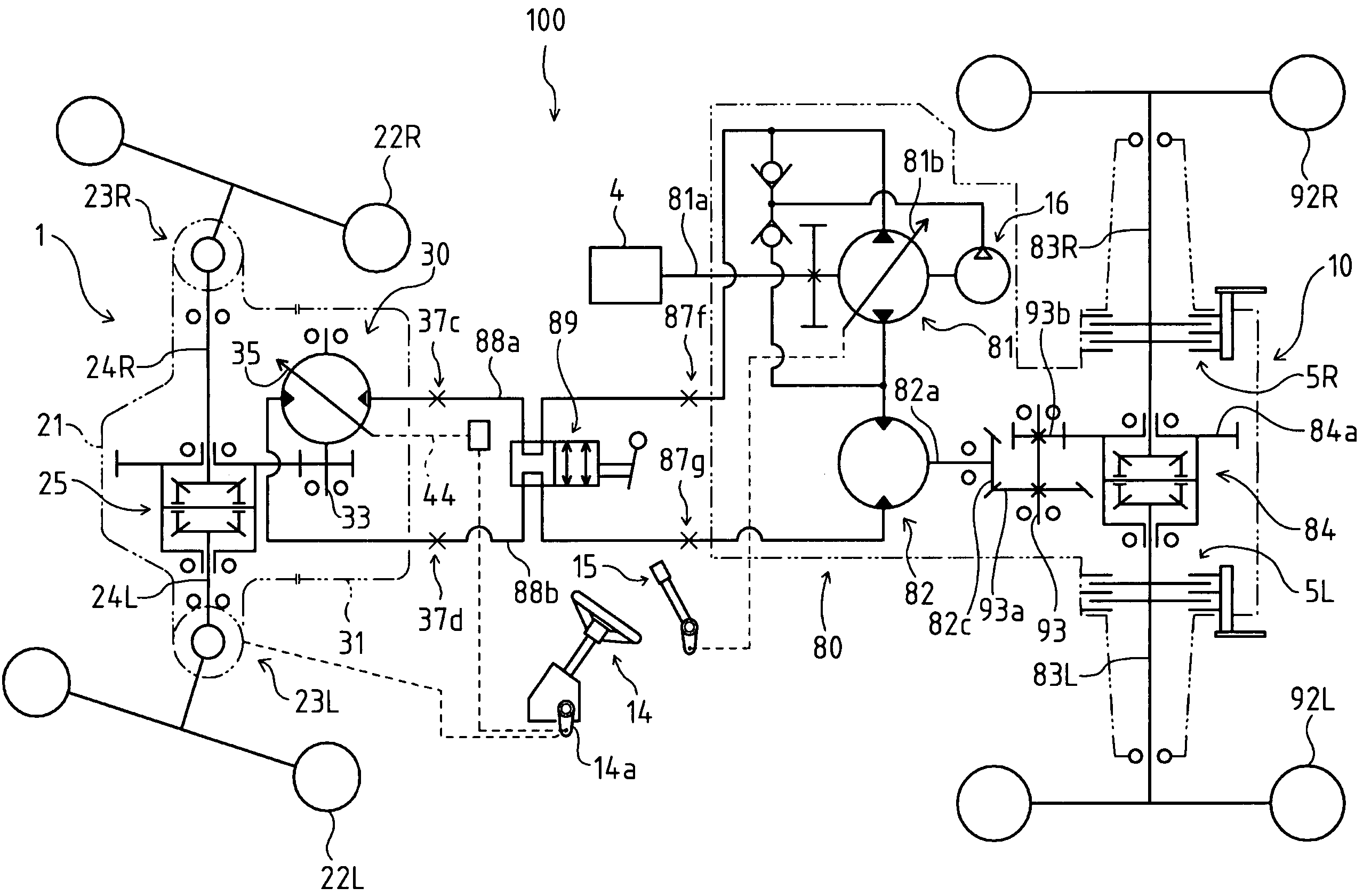
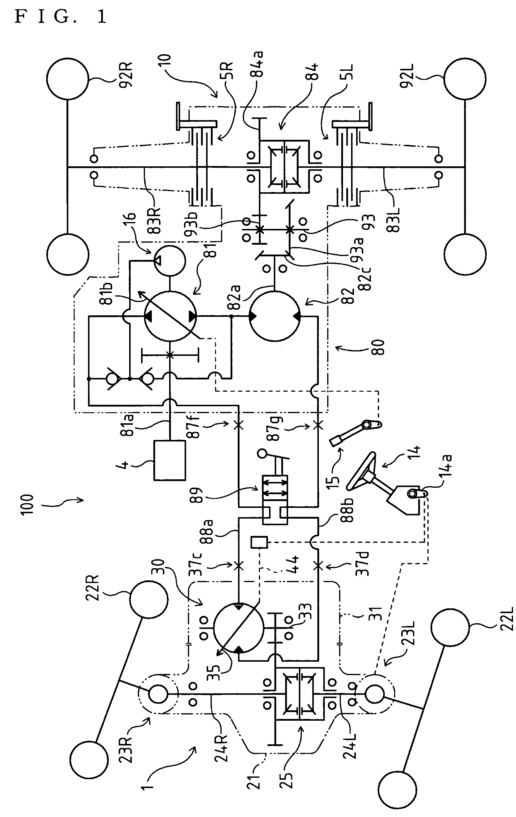
[0053] As shown in FIG. 1, a four-wheel driving vehicle 100 is equipped with a steering transaxle 1 and an unsteering transaxle 10. In the following description, for convenience, steering transaxle 1 is referred to as a front transaxle, and unsteering transaxle 10 as a rear transaxle, however, they may be exchanged in the fore-and-aft direction of vehicle 100. The same is said about later-discussed alternative vehicles.

[0054] Front steering transaxle 1 incorporates a variable displacement hydraulic motor 30 for driving front steerable wheels 22L and 22R, and rear unsteering transaxle 10 is provided with a fixed displacement hydraulic motor 82 for driving rear unsteerable wheels 92L and 92R. Hydraulic motors 30 and 82 are fluidly connected in tandem to a variable displacement hydraulic pump 81 so as to constitute a hydrostatic transmission (HST) circuit for driving four wheels 22L, 22R, 92L and 92R. Hydraulic pump 81 has a movable swash plate 81b operatively connected to a speed con...


PUM


Abstract

A steering transaxle comprises: left and right drive shafts drivingly connected to respective steerable wheels; a differential gear unit differentially connecting the drive shafts to each other; a transaxle casing having an opening, the transaxle casing incorporating the differential gear unit and the drive shafts; a cover for covering the opening of the transaxle casing; a variable hydraulic motor having a movable swash plate, the hydraulic motor being provided on the inside of the cover; a motor control mechanism for controlling the movable swash plate, the motor control mechanism being provided on the outside of the cover; and a hydraulic oil port for oil supply and delivery to and from the hydraulic motor, the hydraulic oil port being provided on the outside of the cover. The cover, the hydraulic motor with the movable swash plate, the motor control mechanism and the hydraulic oil port constitute an assembly unit, which is detachably attached to the transaxle casing so that, by covering the opening with the cover, the hydraulic motor is disposed in the transaxle casing so as to be drivingly connected to the differential gear unit.

Description

BACKGROUND OF THE INVENTION [0001] 1. Field of the Invention [0002] The invention relates to a steering transaxle having a hydraulic motor for driving steerable wheels. The invention also relates to a hydraulic driving vehicle, especially a four-wheel driving vehicle, e.g., an agricultural tractor, a riding mower and a construction machine, comprising the steering transaxle. [0003] 2. Related Art [0004] As disclosed in the Japanese Patent No. 2594951 (document '951) and the Japanese Laid Open Gazettes Nos. 2002-172946 (document '946) and 2000-1127 (document '127), there are conventional well-known four-wheel driving vehicles, each of which has a front steering transaxle and a rear unsteering transaxle. The front steering transaxle supports steerable front wheels and incorporating a front differential gear unit mutually differentially connecting the front wheels, and the rear unsteering transaxle supports unsteerable rear wheels and incorporating a rear differential gear unit mutuall...

Claims


Application Information

Patent Timeline
Patent Type & Authority Applications(United States)
IPC IPC(8): B60K17/10B60K17/30B60K17/356B60K23/08B60T11/21F16H39/04F16H47/02F16H61/42
CPCB60K17/105B60K17/30B60K17/356B60K23/0808B60T11/21Y10T74/2186F16H47/02F16H61/42F16H61/423F16H61/444Y10T74/2188F16H39/04B60W2540/18
Inventor IRIKURA, KOJIISHII, NORIHIROSAKIKAWA, SHIGENORI
Owner KANZAKI KOKYUKOKI MFG
Why Eureka
Try Eureka