Substitution device for aircraft engine

a technology for aircraft engines and substitution devices, which is applied in the direction of machines/engines, ground installations, transportation and packaging, etc., can solve the problems of damage to the engine cover or surrounding elements, and achieve the effect of reducing the footprint of the substitution device and being easy to mov

Inactive Publication Date: 2013-06-13
AIRBUS OPERATIONS (SAS)
View PDF4 Cites 4 Cited by
  • Summary
  • Abstract
  • Description
  • Claims
  • Application Information

AI Technical Summary

Benefits of technology

[0012]Thanks to these arrangements, the protective covers can be closed on the substitution device and can be secured in this position so that the aircraft can be moved on its wheels with no risk of damage to the engine covers.
[0037]According to another aspect of the invention, the substitution device may comprise a hydraulic unit and a sequence unit, and the steps / c1 / and / c2 / can then be carried out under the control of said sequence unit. In this manner, potentially incorrect operations can be avoided.

Problems solved by technology

It is known in the art that when said engine covers are in the open position, the aircraft must not be moved as this could cause damage to the engine covers or surrounding elements.
Moreover, if the engine covers are placed in the closed position (which is the normal position when the engine is running) while the engine is absent, again the aircraft must not be moved as the engine covers could damage each other because they are not held in place by the engine.

Method used


Image

  • Substitution device for aircraft engine
  • Substitution device for aircraft engine
  • Substitution device for aircraft engine

Examples


Embodiment Construction

[0048]When the same reference symbols are used in different figures, they designate the same or similar elements.

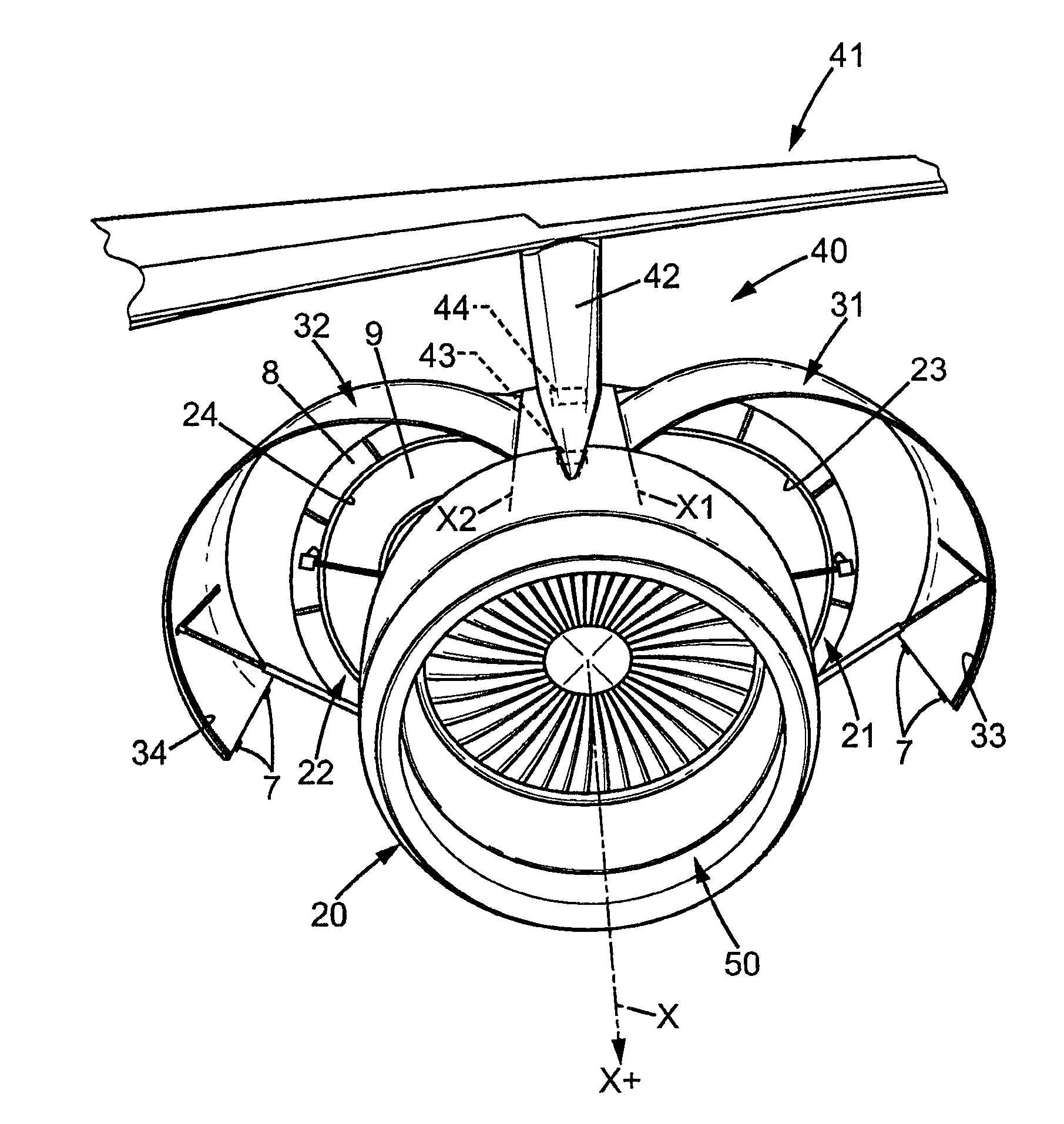
[0049]Throughout the entire description below, by convention, the terms “front” and “rear” are with respect to the direction of travel of an aircraft resulting from thrust exerted by its engines; this direction corresponds to the X pluses (X+).

[0050]FIG. 1 schematically illustrates a propulsion system 40 for an aircraft. In the illustrated example, said propulsion system 40 comprises a turbo device of the turbojet type of engine, which will hereinafter be generically referred to as an “engine”50.

[0051]The propulsion system 40 includes an engine support mast 42, which connects the engine 50 to the wing 41 of the aircraft. In the configuration shown in the example, the engine is arranged below the wing, and generally the engine is offset forward relative to the wing. In addition, the engine support mast 42 comprises at least two engine mounts 43, 44 used to affix the engine...


PUM


Abstract

A substitution device for replacing a turbojet type of aircraft engine, with a nacelle comprising protective covers, and a support mast having two engine mounts, each of said protective covers being mounted to pivot between an open position and a closed position, said substitution device comprising a body, two anchors attaching to the engine mounts of the engine support mast, and bearing portions adapted to receive support portions belonging to the protective covers. A method for installing such a substitution device in a nacelle, which makes it possible to close the engine covers and authorize the movement of the aircraft.

Description

TECHNICAL FIELD[0001]The present invention relates to substitution devices for an aircraft engine, in particular for turbojet engines.[0002]These substitution devices can be considered as support tools to assist with aircraft construction and maintenance. Under normal circumstances, such aircraft engines are usually attached to a supporting mast and protected by a nacelle which includes cowls (protective covers) surrounding the engine.PRIOR ART TECHNOLOGY[0003]According to known prior art, one (or several) engines must sometimes be removed for maintenance on said engine or for engine replacement. However, in order to remove an engine, it is first necessary to open the engine covers which are part of the nacelle. It is known in the art that when said engine covers are in the open position, the aircraft must not be moved as this could cause damage to the engine covers or surrounding elements. Moreover, if the engine covers are placed in the closed position (which is the normal positio...

Claims


Application Information

Patent Timeline
Patent Type & Authority Applications(United States)
IPC IPC(8): F02C7/20
CPCB64F5/0036F02C7/20B64F5/50
Inventor GARRIC, STEPHANEVIGNEAU, PHILIPPE
Owner AIRBUS OPERATIONS (SAS)
Why Eureka
Try Eureka