Light Emitting Apparatus

Inactive Publication Date: 2013-06-13
GIO OPTOELECTRONICS CORP
View PDF5 Cites 76 Cited by
  • Summary
  • Abstract
  • Description
  • Claims
  • Application Information

AI Technical Summary

Benefits of technology

[0035]As mentioned above, the light emitting apparatus according to the invention utilizes the sensing unit to sense the filament currents flowing between two electrical input terminals of the first electrical connection element and between two electrical input terminals of the second electrical connection element, and then controls the switching unit to turn on and enable the light emitting unit to start to emit light. Thus, when the user only installs the first electrical connection element in the lamp holder,

Problems solved by technology

So, when the user inadvertently touches the electrical connect

Method used


Image

  • Light Emitting Apparatus
  • Light Emitting Apparatus
  • Light Emitting Apparatus

Examples


Embodiment Construction

[0044]The present invention will be apparent from the following detailed description, which proceeds with reference to the accompanying drawings, wherein the same references relate to the same elements.

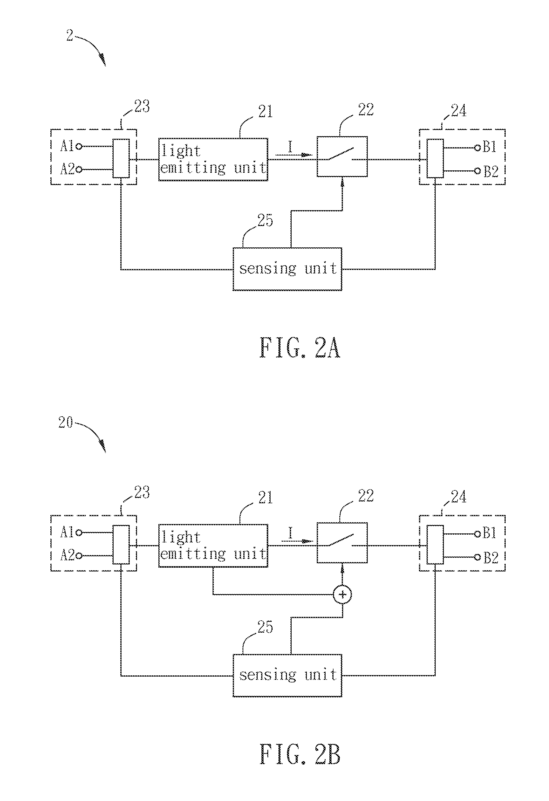
[0045]FIG. 2A is a schematic illustration showing a light emitting apparatus 2 according to a preferred embodiment of the invention.

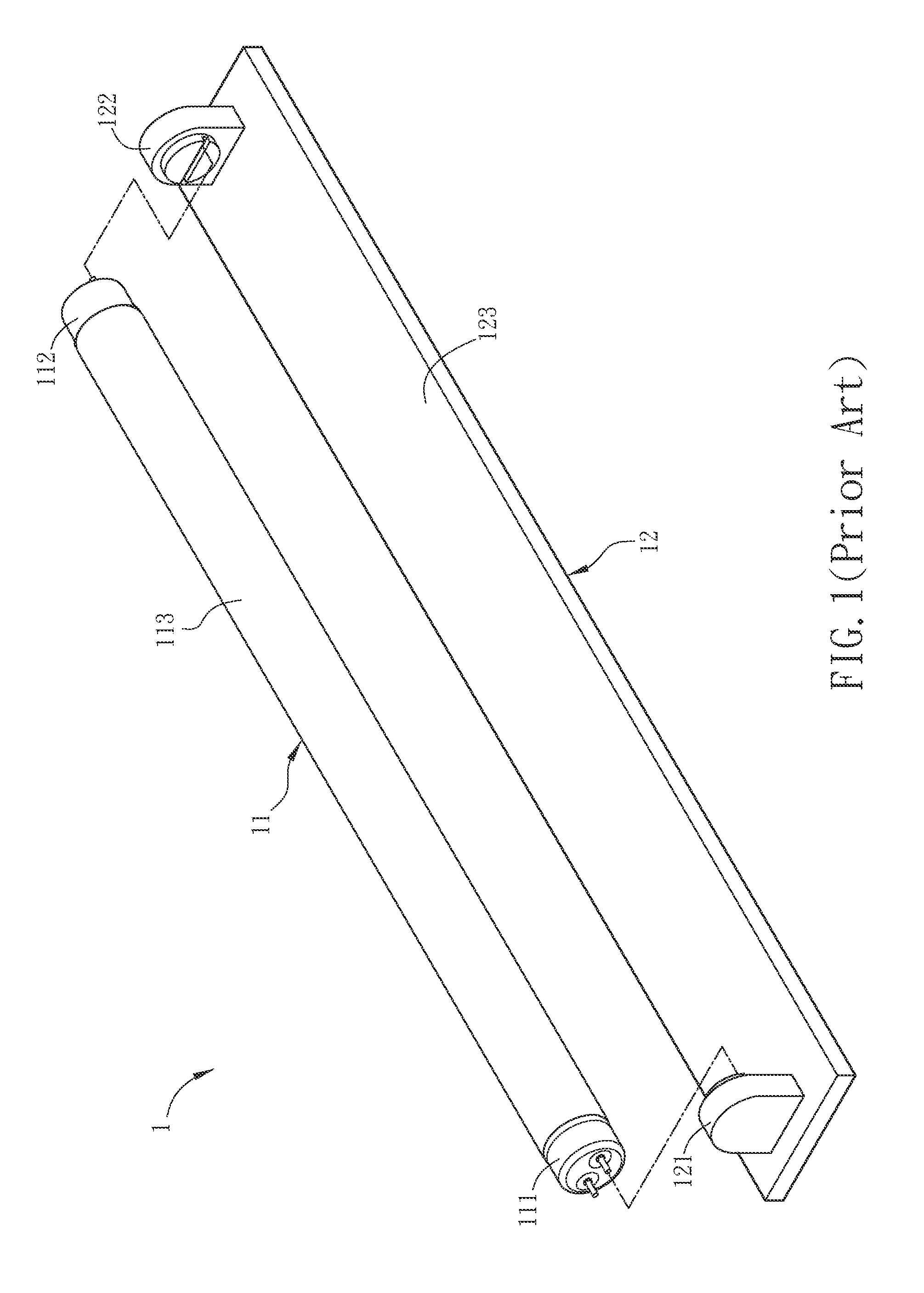
[0046]It is to be specified that a light emitting apparatus 2 of the invention is not restricted to be compatible with the conventional longitudinal daylight lamp (also referred to as a fluorescent lamp) to replace only the conventional daylight lamp. In other embodiments, the light emitting apparatus 2 may have another aspect to replace the other daylight lamps with another shape, such as the lamp with the circular shape, the mosquito coil shape, the rectangular shape or any other shape. Herein, the invention is not particularly restricted thereto. Nevertheless, in order to replace the conventional daylight lamp, the light emitting apparatus 2 may be mad...


PUM


Abstract

A light emitting apparatus receives an external power. A switching unit is electrically connected with a light emitting unit to form a serial circuit. A first electrical connection element is electrically connected with the external power and the light emitting unit. A second electrical connection element is electrically connected with the external power and the switching unit. A sensing unit is electrically connected with the first electrical connection element, the second electrical connection element and the switching unit. When filament currents flow between two electrical input terminals of the first electrical connection element and between two electrical input terminals of the second electrical connection element, the sensing unit controls the switching unit to turn on to enable the light emitting unit to receive the external power and start to emit light. Thus, users can avoid the risk of electric shock when installing the light emitting apparatus.

Description

CROSS REFERENCE TO RELATED APPLICATIONS[0001]This Non-provisional application claims priority under 35 U.S.C. §119(a) on Patent Application No(s). 100145618 filed in Taiwan, Republic of China on Dec. 9, 2011, the entire contents of which are hereby incorporated by reference.BACKGROUND OF THE INVENTION[0002]1. Field of Invention[0003]The present invention relates to a light emitting apparatus and, in particular, to a light emitting apparatus with light emitting diodes (LEDs).[0004]2. Related Art[0005]Recently, the manufacturing processes and materials of the light emitting diode (LED) are continuously improved, so the light emitting efficiency of the LED is also significantly improved. Comparing to the typical fluorescent lamp or power-saving light bulb, the LED has the properties of lower power consumption, lower pollution, longer lifetime, higher safety, shorter light emitting response time and smaller size. Therefore, the LEDs have become widely used in many electronic products an...

Claims


Application Information

Patent Timeline
IPC IPC(8): F21V25/00H05B44/00
CPCY02B20/383F21Y2103/003H05B33/0809H05B33/0884F21V25/04F21Y2101/02F21V25/00F21K9/175F21K9/27F21Y2103/10F21Y2115/10H05B45/50Y02B20/30H05B45/42H05B47/26
Inventor YANG, WU-CHANG
Owner GIO OPTOELECTRONICS CORP
Why Eureka
Try Eureka