Three-dimensional image generating method, three-dimensional image generating apparatus, and display apparatus provided with same

Inactive Publication Date: 2013-06-13
SHARP KK
View PDF3 Cites 17 Cited by
  • Summary
  • Abstract
  • Description
  • Claims
  • Application Information

AI Technical Summary

Benefits of technology

[0036]According to the first aspect, a three-dimensional image that produces a significant stereoscopic effect can be generated by simple computation to calculate luminance gradients between pixels of interest and starting-point pixels, without requiring complicated computation to calculate depth information. Moreover, luminance corrections are simply performed, so that pixel positions do not change, and therefore, output images (typically, left-eye and right-eye images) can be prevented from appearing doubled, or can be rendered resistant to appearing doubled, when the images are displayed (for example, in an alternating manner). In addition, as a result, any viewer without an active shutter (any viewer other than the user thereof) can readily recognize the content of an image on, for example, a 3D television apparatus or suchlike of a frame sequential type, and therefore would not have an unpleasant feeling.
[0037]According to the second aspect, the correction amount is set such that its absolute value increases as the absolute value of the luminance gradient increases, and therefore, the stereoscopic effect can be enhanced where the luminance changes sharply.
[0038]According to the third aspect, when the absolute value of the luminance gradient is greater than or equal to the predetermined threshold, the correction amount is set to zero considering the pixel of interest to be included at an edge, and therefore, it is possible to avoid luminance changes to an abnormally great extent near the edge, and also

Problems solved by technology

However, two-dimensional images (planar images) provided by general television broadcasting are not designed to be stereoscopically d

Method used


Image

  • Three-dimensional image generating method, three-dimensional image generating apparatus, and display apparatus provided with same
  • Three-dimensional image generating method, three-dimensional image generating apparatus, and display apparatus provided with same
  • Three-dimensional image generating method, three-dimensional image generating apparatus, and display apparatus provided with same

Examples


first embodiment

1. First Embodiment

[0064]

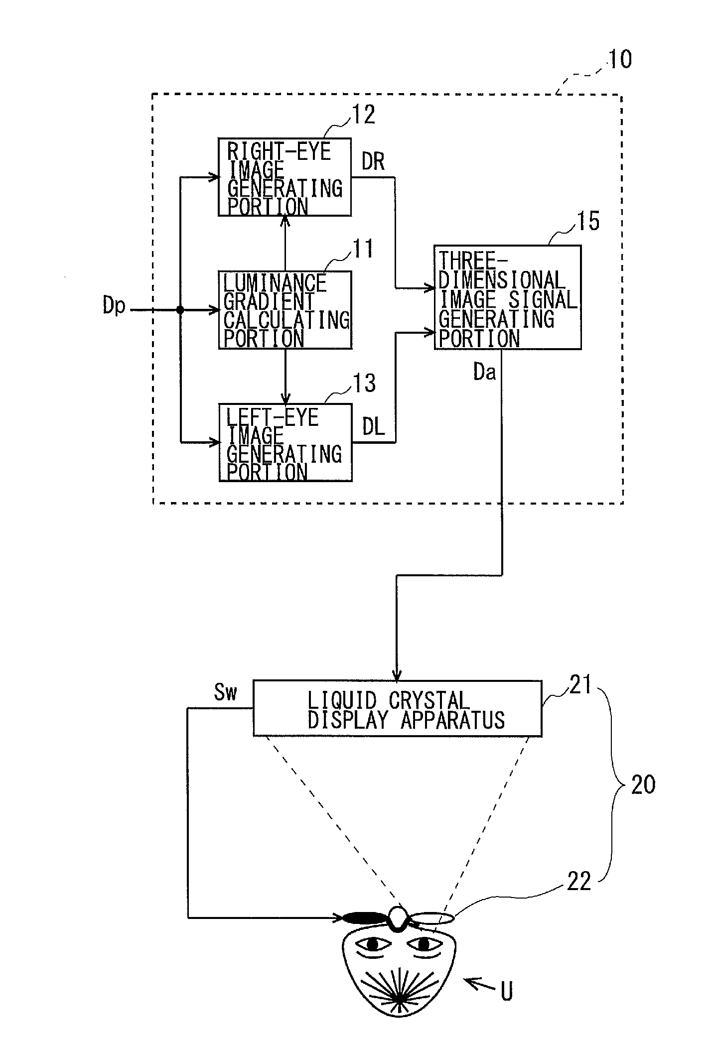
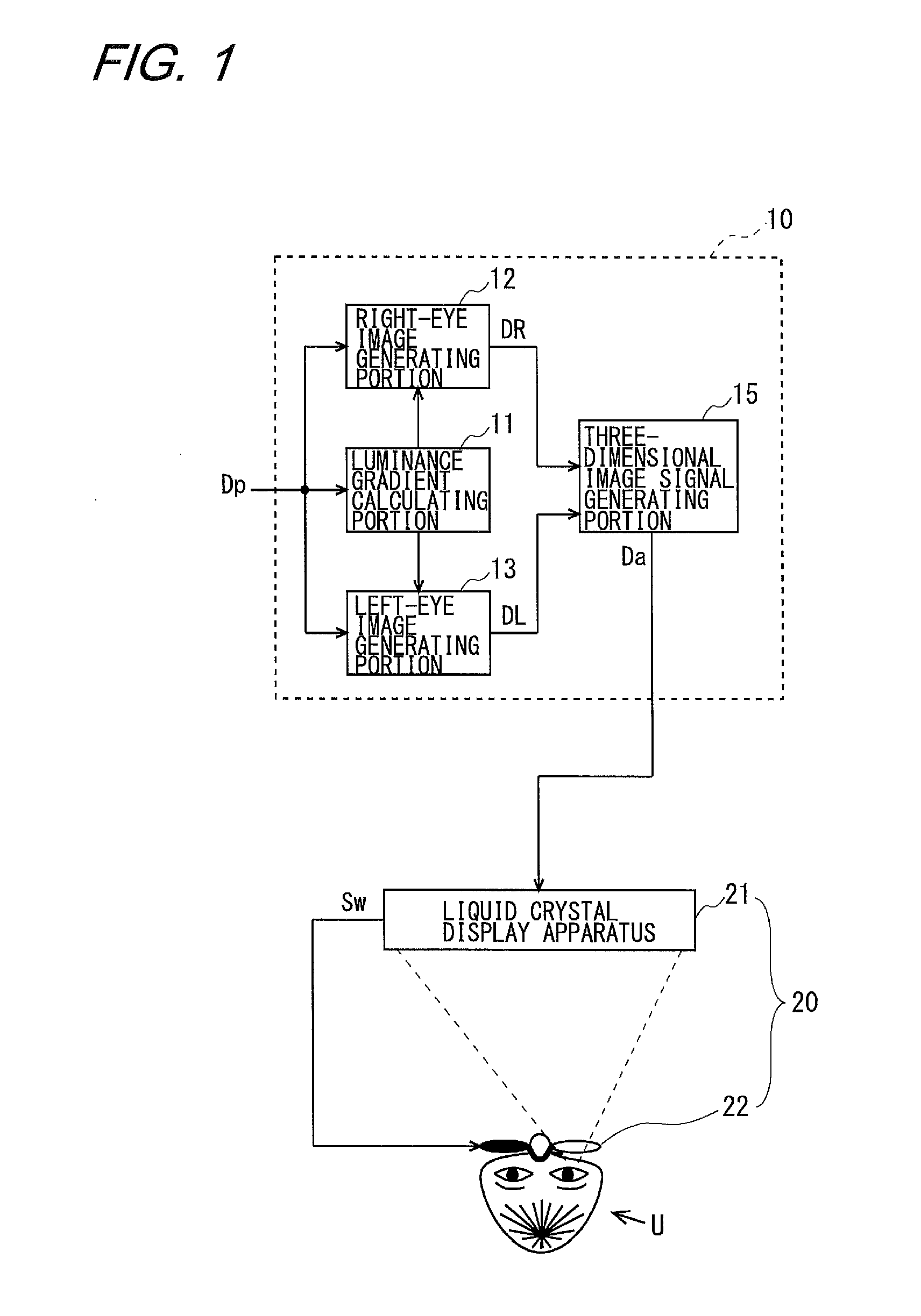
[0065]FIG. 1 is a block diagram illustrating the configuration of a three-dimensional image generating apparatus according to a first embodiment of the present invention. As shown in FIG. 1, the three-dimensional image generating apparatus 10 includes a luminance gradient calculating portion 11 for externally receiving a video signal Dp, which includes a planar image (two-dimensional image), and calculating luminance gradients between adjacent pixels in the planar image, a right-eye image generating portion 12 for generating a right-eye image DR on the basis of the planar image and the luminance gradients, a left-eye image generating portion 13 for generating a left-eye image DL on the basis of the planar image and the luminance gradients, and a three-dimensional image signal generating portion 15 for generating a three-dimensional image signal Da from the right-eye image DR and the left-eye image DL. Note that as will be described below, in the present inve...

second embodiment

2. Second Embodiment

[0092]

[0093]FIG. 6 is a block diagram illustrating the configuration of a three-dimensional image generating apparatus according to a second embodiment of the present invention. The three-dimensional image generating apparatus 30 shown in FIG. 6 includes a luminance gradient calculating portion 31 for externally receiving a planar image (two-dimensional image) Dp and calculating luminance gradients, in the same manner as in the luminance gradient calculating portion 11 of the first embodiment, a right-eye image generating portion 32 for generating a right-eye image DR on the basis of the planar image Dp and the luminance gradients, in the same manner as in the right-eye image generating portion 12 of the first embodiment, and a three-dimensional image signal generating portion 35 for generating a three-dimensional image signal Da on the basis of the right-eye image DR and the planar image, and the left-eye image generating portion 13 for generating the left-eye i...

third embodiment

3. Third Embodiment

[0101]

[0102]FIG. 7 is a block diagram illustrating the configuration of a three-dimensional image generating apparatus according to a third embodiment of the present invention. As shown in FIG. 7, the three-dimensional image generating apparatus 40 includes a three-dimensional image signal separating portion 44 for externally receiving a three-dimensional image signal DpLR, which includes a three-dimensional image, and outputting an external right-eye image DpR and an external left-eye image DpL after separating the images, a right-eye luminance gradient calculating portion 46 for receiving the external right-eye image DpR from the three-dimensional image signal separating portion 44 and calculating right-eye luminance gradients, a right-eye image generating portion 42 for generating a right-eye image DR on the basis of the external right-eye image DpR and the right-eye luminance gradients, a left-eye luminance gradient calculating portion 47 for receiving the ext...


PUM


Abstract

In a three-dimensional image generating apparatus, a luminance gradient calculating portion calculates a luminance gradient, which indicates the amount of change in luminance between a pixel of interest and a pixel adjacent thereto, a right-eye image generating portion corrects a pixel luminance in a correction amount having the same sign as the luminance gradient, and a left-eye image generating portion corrects a pixel luminance in a correction amount having the opposite sign to the luminance gradient. As a result, there is a difference in luminance distribution between left-eye and right-eye images, so that stereoscopic viewing is made possible without calculating depth information, and there is no change in pixel positions, so that the images do not appear doubled or they are resistant to appearing doubled.

Description

TECHNICAL FIELD[0001]The present invention relates to three-dimensional image generating methods, particularly to a method for generating a stereoscopically viewable, three-dimensional image from a planar (two-dimensional) image, and the invention also relates to an apparatus for generating such an image and a display apparatus including the same.BACKGROUND ART[0002]Recently, there are sold a variety of display apparatuses that allow stereoscopic viewing, such as 3D television apparatuses. The 3D television apparatus provides stereoscopic display on the basis of a video source, such as a 3D movie, designed to be stereoscopically displayable.[0003]However, two-dimensional images (planar images) provided by general television broadcasting are not designed to be stereoscopically displayable, and therefore, there is demand to generate stereoscopically displayable, three-dimensional images from such planar images.[0004]There are various conventional techniques to convert planar images to...

Claims


Application Information

Patent Timeline
IPC IPC(8): G06T15/00
CPCH04N13/026G06T15/00H04N2213/006H04N13/261
Inventor TANAKA, YUHJI
Owner SHARP KK
Why Eureka
Try Eureka