
Reinforced Stators and Fabrication Methods

a technology of reinforced stators and fabrication methods, which is applied in the direction of manufacturing tools, machines/engines, liquid fuel engines, etc., can solve the problems of significantly reducing the efficiency of pc motors or pumps, affecting the performance of pc pumps or motors, and increasing the operating temperature of stator inserts

Active Publication Date: 2013-06-13
NAT OILWELL VARCO LP
View PDF22 Cites 50 Cited by
  • Summary
  • Abstract
  • Description
  • Claims
  • Application Information

AI Technical Summary

Benefits of technology

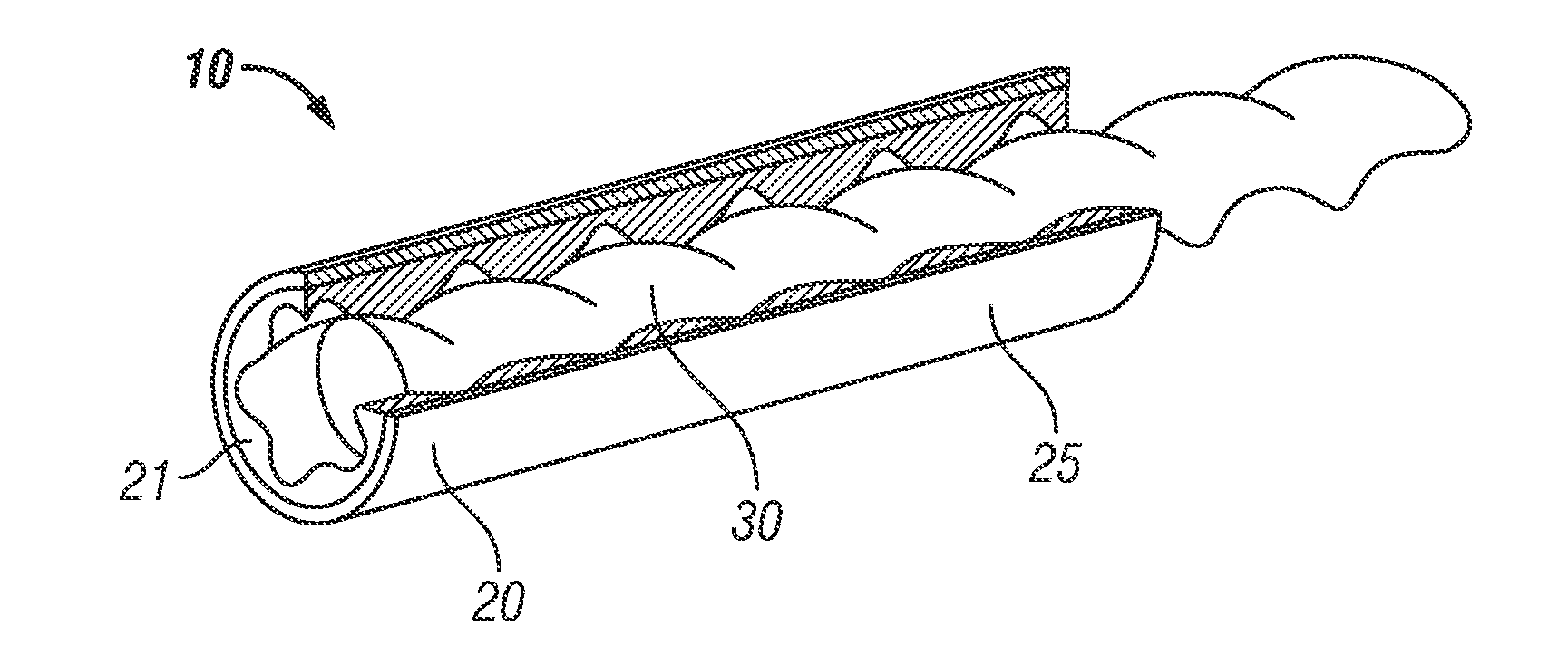
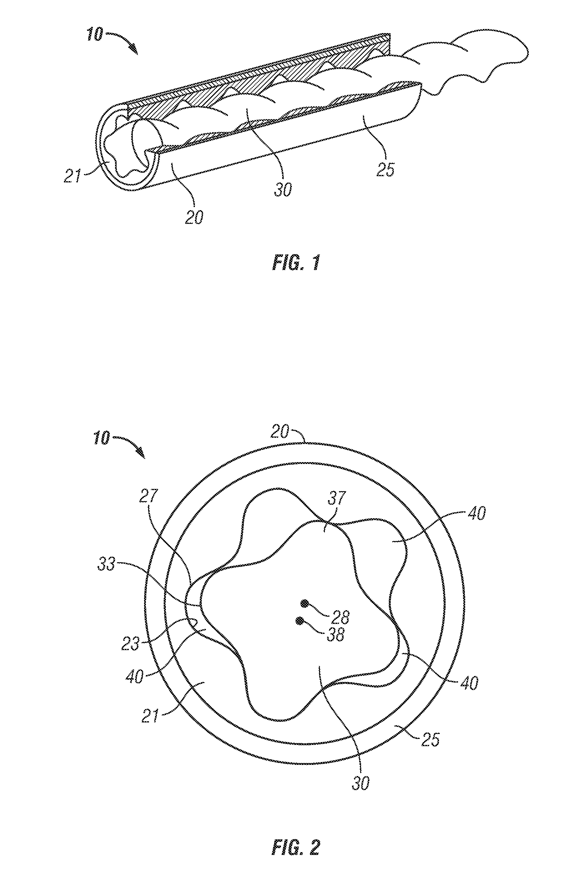
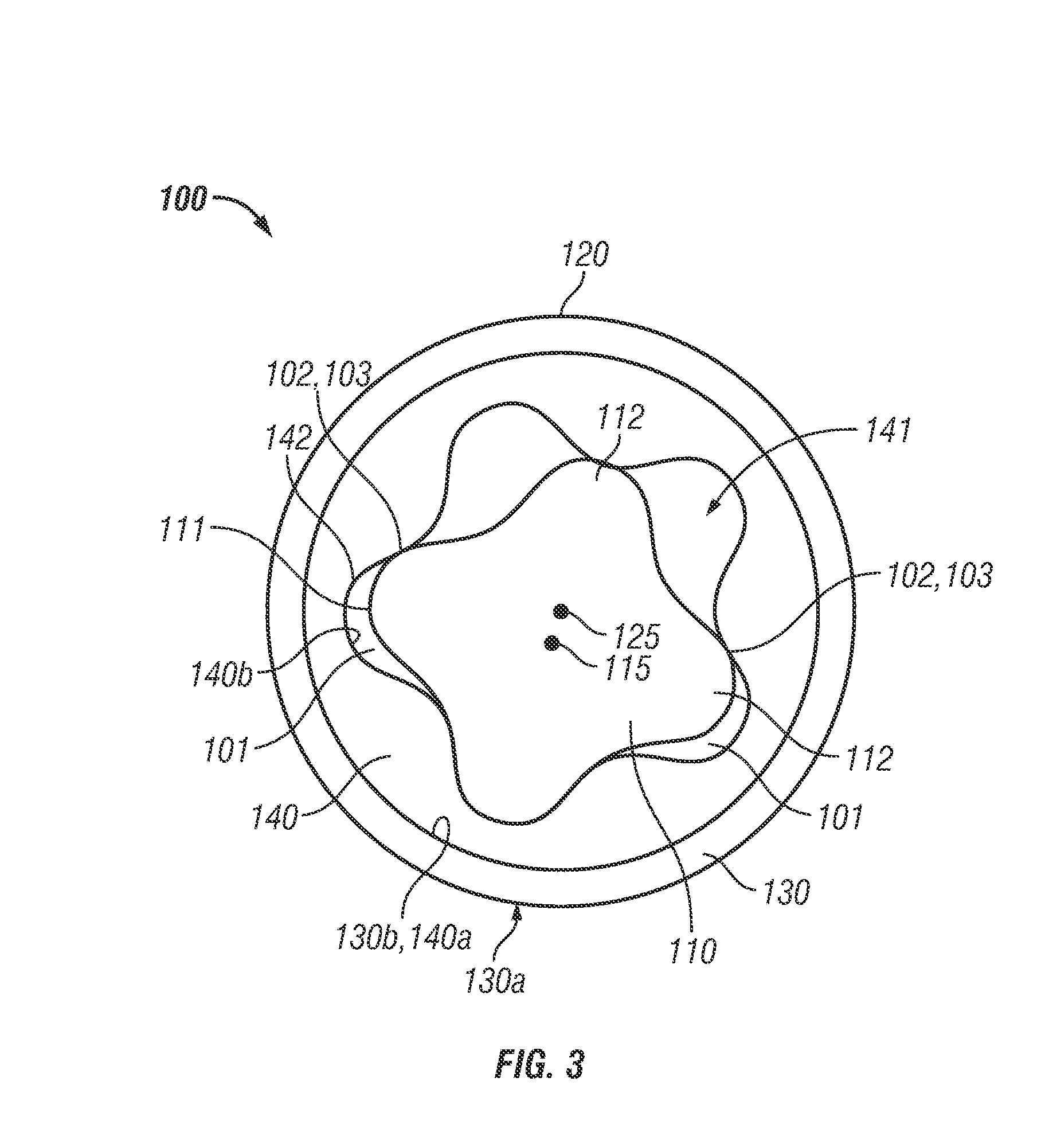
The patent describes a stator for a progressive cavity pump or motor that has a reinforcement structure with voids dispersed throughout it. This stator is made up of a tubular housing and a stator insert coaxially placed inside the housing. The stator insert is attached to the housing with an elastomeric insert liner. The stator has a central axis and a helical-shaped throughbore extending axially through it, with a rotor rotatably disposed within it. This design provides improved performance and efficiency of the pump or motor.

Problems solved by technology

The cyclic deflections and frictional engagement of the rotor and stator are known to cause increases in the operating temperature of the stator insert.
Although some of the thermal energy generated in the stator insert is carried off by the fluid medium flowing through the PC pump or motor (e.g., drilling mud), a substantially amount of thermal energy remains in the stator and can negatively impact performance of the PC pump or motor.
For example, the elastomeric material of the stator insert may expand to the extent that frictional losses due to engagement of the rotor and the stator begin to significantly reduce the efficiency of PC motor or pump.
Even worse, in some cases, the elastomeric stator liner may expand to the extent that rotation of the rotor is completely inhibited.
In addition, excessive frictional engagement between the rotor and the stator may strip away the liquid between the rotor and stator, potentially leading to a dry contact region and resulting damage to the elastomeric material.

Method used


Image

  • Reinforced Stators and Fabrication Methods
  • Reinforced Stators and Fabrication Methods
  • Reinforced Stators and Fabrication Methods

Examples


Embodiment Construction

[0026]The following discussion is directed to various embodiments of the invention. Although one or more of these embodiments may be preferred, the embodiments disclosed should not be interpreted, or otherwise used, as limiting the scope of the disclosure, including the claims. In addition, one skilled in the art will understand that the following description has broad application, and the discussion of any embodiment is meant only to be exemplary of that embodiment, and not intended to intimate that the scope of the disclosure, including the claims, is limited to that embodiment.

[0027]Certain terms are used throughout the following description and claims to refer to particular features or components. As one skilled in the art will appreciate, different persons may refer to the same feature or component by different names. This document does not intend to distinguish between components or features that differ in name but not function. The drawing figures are not necessarily to scale...


PUM

PropertyMeasurementUnit
Elastomericaaaaaaaaaa

Abstract

A stator for a progressive cavity pump or motor comprises a tubular housing having a central axis. In addition, the stator comprises a stator insert coaxially disposed within the housing. The stator insert has a radially outer surface that engages the housing and a radially inner surface defining a helical-shaped through bore extending axially through the stator insert. The stator insert includes an insert body and an insert liner attached to the insert body. The insert body is radially positioned between the housing and the insert liner. The insert body comprises a reinforcement structure and a plurality of voids dispersed within the reinforcement structure.

Description

CROSS-REFERENCE TO RELATED APPLICATIONS[0001]This application is a 35 U.S.C.§371 national stage application of PCT / US2011 / 047745 filed Aug. 15, 2011, which claims benefit of U.S. provisional patent application Ser. No. 61 / 373,960 filed Aug. 16, 2010, and entitled “Reinforced Stators and Fabrication Methods,” each of which is hereby incorporated herein by reference in its entirety.BACKGROUND[0002]1. Field of the Invention[0003]The invention relates generally to pumps and motors that have a rotor rotatably disposed within a stator. More particularly, the invention relates to reinforced stators for pumps and motors and methods of fabricating the same.[0004]2. Background of the Technology[0005]A progressive cavity pump (PC pump), also know as a “Moineau” pump, transfers fluid by means of a sequence of discrete cavities that move through the pump as a rotor is turned within a stator. Transfer of fluid in this manner results in a volumetric flow rate proportional to the rotational speed o...

Claims


Application Information

Patent Timeline
IPC IPC(8): F01C1/22
CPCF04C2/1075Y10T29/49826F01C1/22B33Y80/00H02K5/04H02K15/14
Inventor SRESHTA, HAROLD A.SUE, JIINJEN ALBERTBUTUC, STEFAN M.MARSHALL, JAN EDGAR
Owner NAT OILWELL VARCO LP
Learn More