Inflatable Robots, Robotic Components and Assemblies and Methods Including Same

a robot and robot body technology, applied in the field of robots and components thereof, can solve the problems of affecting the integration and wide acceptance of the robot, affecting the safety of the robot, and high cost,

Inactive Publication Date: 2013-06-20
IROBOT CORP
View PDF4 Cites 84 Cited by
  • Summary
  • Abstract
  • Description
  • Claims
  • Application Information

AI Technical Summary

Benefits of technology

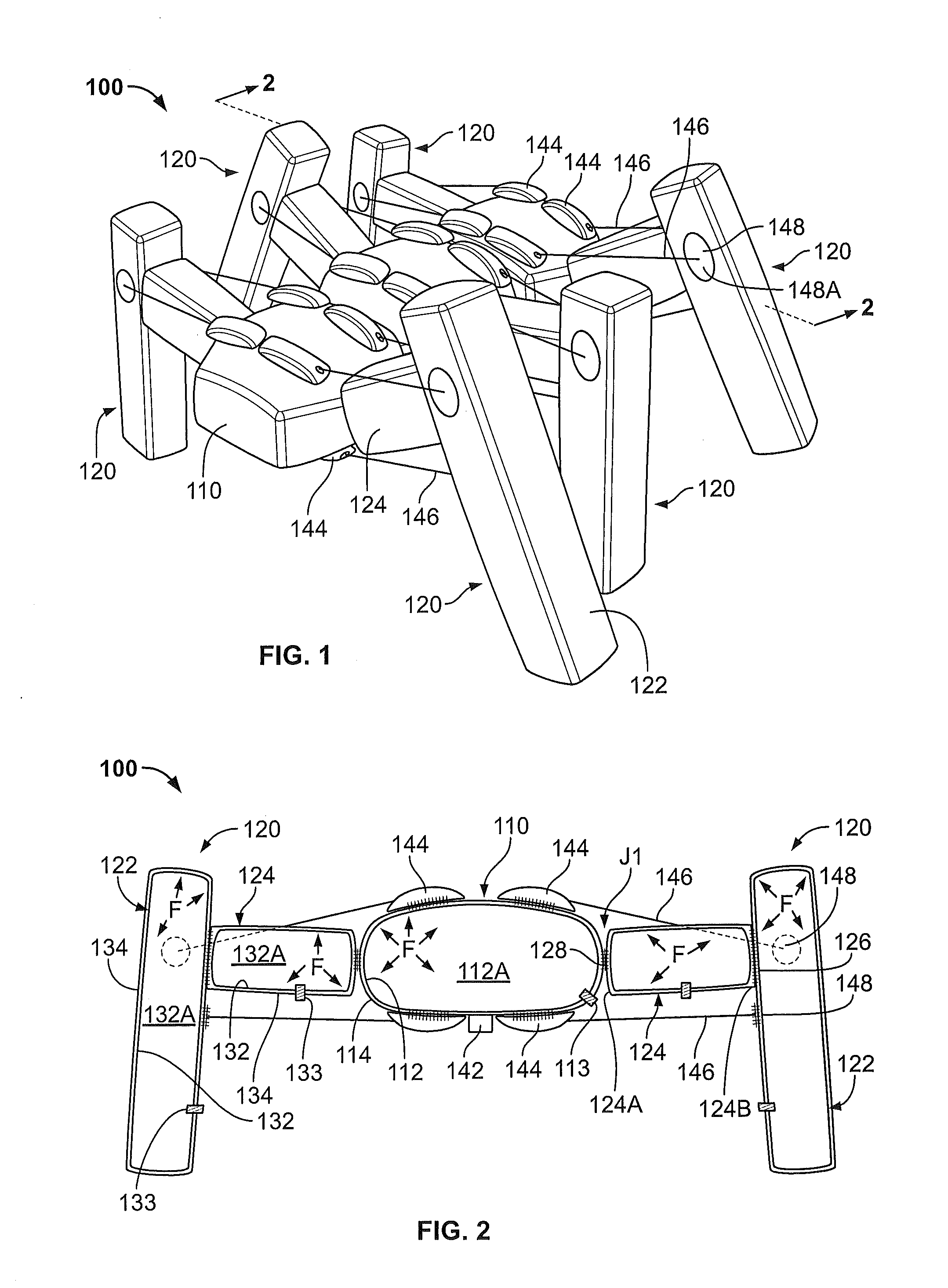
[0010]According to some embodiments, the rolling flexure joint includes at least one flexible collateral ligament secured to each of the first and second structural members to provide torsional and lateral stability to the rolling flexure joint.
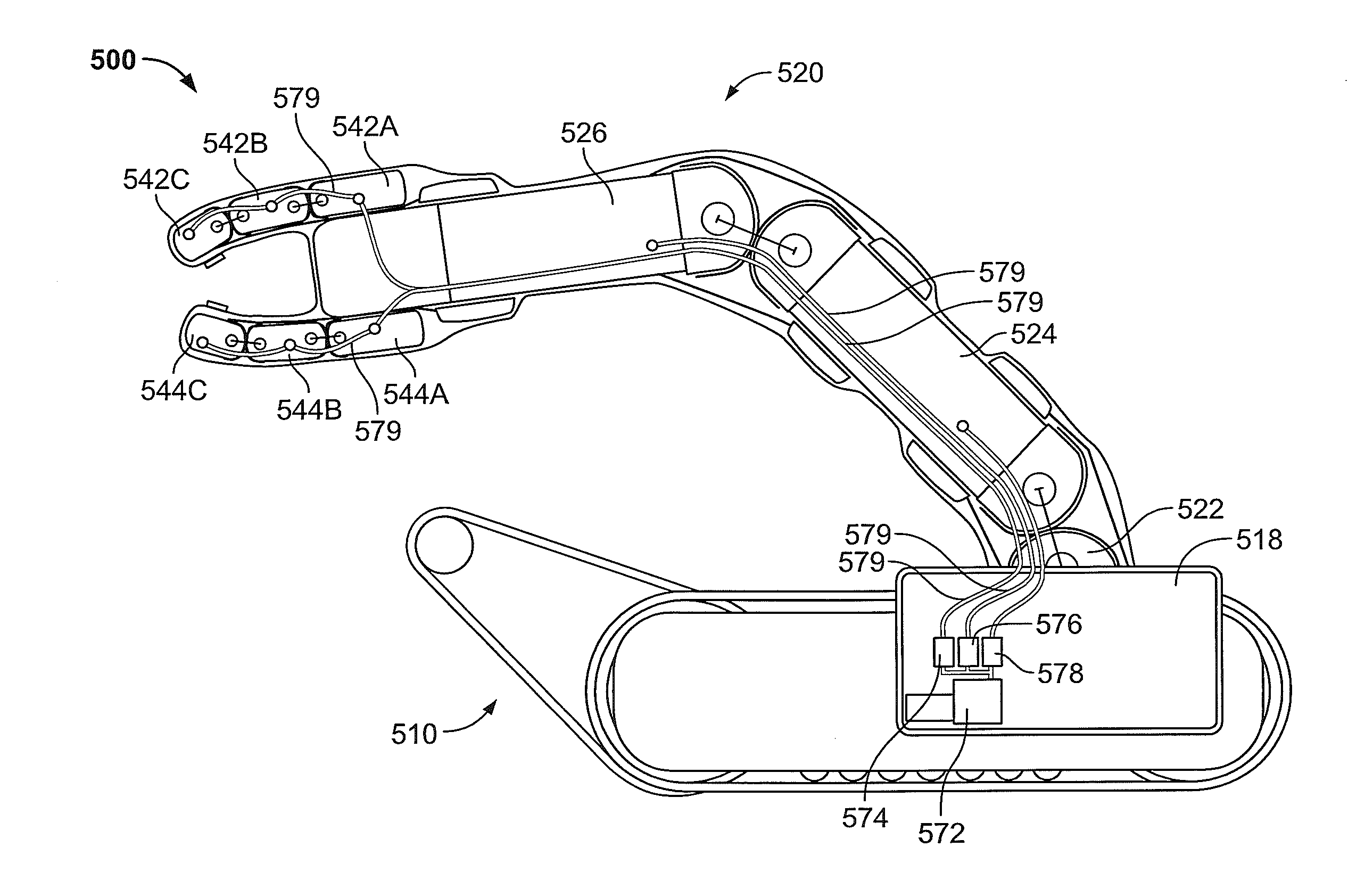
[0012]In some embodiments, the first finger has first and second, relatively moveable, inflatable phalanges. The inflatable robotic assembly may include a rolling flexure joint joining the first and second phalanges to provide at least one degree of freedom between the first and second phalanges. According to some embodiments, the inflatable robotic assembly includes a second rolling flexure joint joining the first finger and the support member to provide at least one degree of freedom between the first finger and the support member.

Problems solved by technology

However, their further integration and wide acceptance may be impeded by high weight, low packing density, high cost, and safety concerns.

Method used


Image

  • Inflatable Robots, Robotic Components and Assemblies and Methods Including Same
  • Inflatable Robots, Robotic Components and Assemblies and Methods Including Same
  • Inflatable Robots, Robotic Components and Assemblies and Methods Including Same

Examples


Embodiment Construction

[0045]The present invention now will be described more fully hereinafter with reference to the accompanying drawings, in which illustrative embodiments of the invention are shown. In the drawings, the relative sizes of regions or features may be exaggerated for clarity. This invention may, however, be embodied in many different forms and should not be construed as limited to the embodiments set forth herein; rather, these embodiments are provided so that this disclosure will be thorough and complete, and will fully convey the scope of the invention to those skilled in the art.

[0046]It will be understood that when an element is referred to as being “coupled” or “connected” to another element, it can be directly coupled or connected to the other element or intervening elements may also be present. In contrast, when an element is referred to as being “directly coupled” or “directly connected” to another element, there are no intervening elements present. Like numbers refer to like elem...


PUM


Abstract

A robotic joint assembly includes a first structural member, a second structural member, and a rolling flexure joint joining the first structural member to the second structural member to provide at least one degree of freedom between the first and second structural members. The rolling flexure joint includes first and second flexible hinge members each having one end secured to the first structural member and an opposing end secured to the second structural member. The first and second flexible hinge members cross one another between the first and second structural members.

Description

RELATED APPLICATION(S)[0001]This application claims the benefit of and priority from U.S. Provisional Patent Application Ser. No. 61 / 617,864, filed Mar. 30, 2012, and claims the benefit of and priority from U.S. Provisional Patent Application Ser. No. 61 / 577,114, filed Dec. 19, 2011, the disclosures of which are incorporated herein by reference in their entireties.STATEMENT OF GOVERNMENT SUPPORT[0002]This invention was made with support under Defense Advanced Research Projects Agency (DARPA) Contract No. W91CRB-11-C-0050 awarded by DARPA with Army Research, Development and Engineering Command (RDECOM). The Government has certain rights in the invention.FIELD OF THE INVENTION[0003]The present invention relates to robots and components thereof.BACKGROUND[0004]Robots, including mobile robots, have been successfully integrated into military, industrial, and commercial settings. However, their further integration and wide acceptance may be impeded by high weight, low packing density, hig...

Claims


Application Information

Patent Timeline
Patent Type & Authority Applications(United States)
IPC IPC(8): B25J17/00B25J15/00
CPCB25J17/00B25J15/0009Y10S901/01Y10T74/20329B25J9/0015B25J9/142B62D57/032B25J5/005B25J18/06
Inventor MOZEIKA, ANNAN MICHAELCLAFFEE, MARK ROBERTBUEHLER, MARTIN
Owner IROBOT CORP
Why Eureka
Try Eureka