Heat exchanger

Inactive Publication Date: 2013-06-20
ROLLS ROYCE PLC
View PDF10 Cites 17 Cited by
  • Summary
  • Abstract
  • Description
  • Claims
  • Application Information

AI Technical Summary

Benefits of technology

[0017]One or more of the summits may provide a seat portio

Problems solved by technology

The complex flow patterns aid the heat transfer between the hot and cold air flows but at a penalty of increasin

Method used


Image

  • Heat exchanger
  • Heat exchanger
  • Heat exchanger

Examples


Embodiment Construction

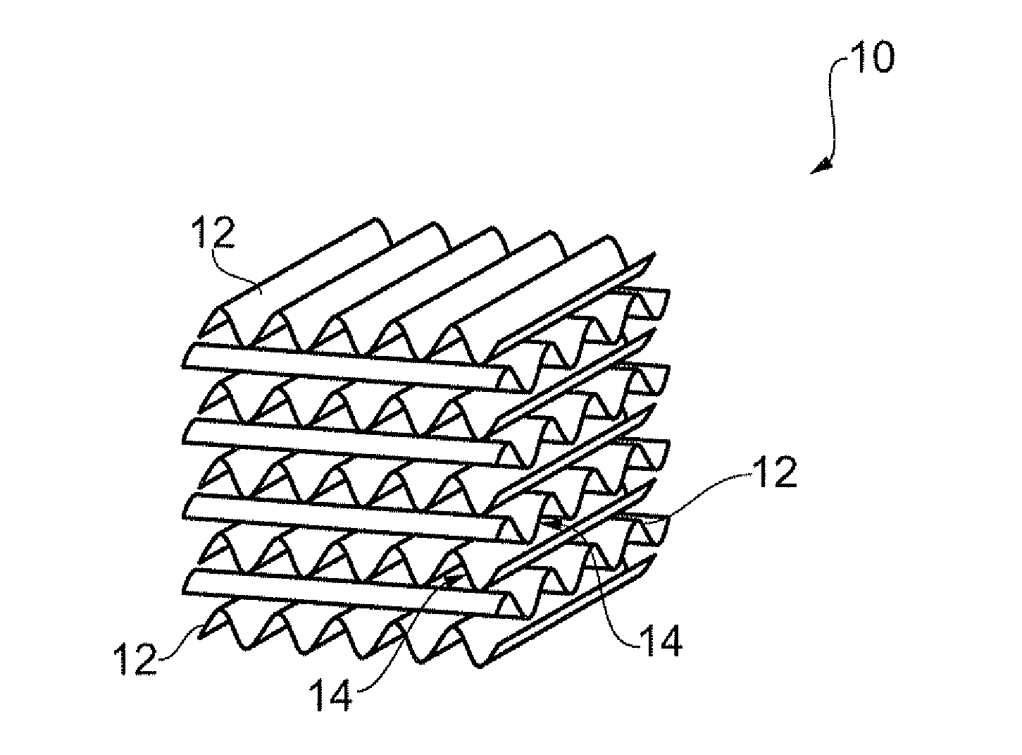
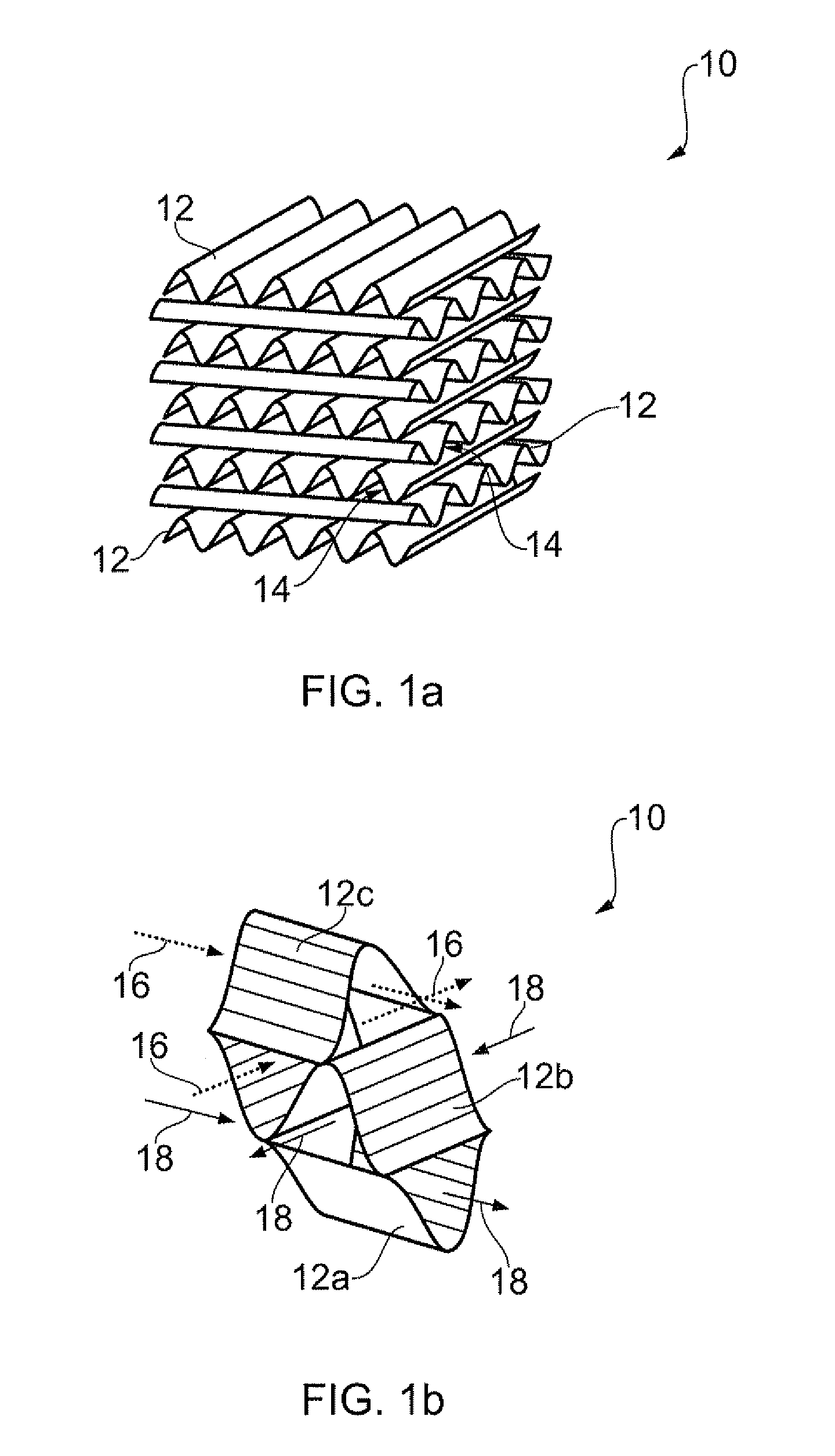
[0036]Corrugated plate heat exchanger matrices typically have high thermal transfer coefficients and good pneumatic performance. However, conventional corrugated plate matrices have non-uniform heat transfer coefficients across the surface of each corrugated plate, with, for example, a lower heat transfer coefficient in a trough of the corrugations. This non-uniformity in heat transfer results in a non-uniform temperature distribution in the heat exchanger plates and a reduction in performance as a consequence. A typical figure for this reduction in performance can be as high as 7%, which is unnecessarily high. Further, the non-uniformity of heat transfer can lead to local thermal stresses in the heat exchanger matrix which are generally undesirable.

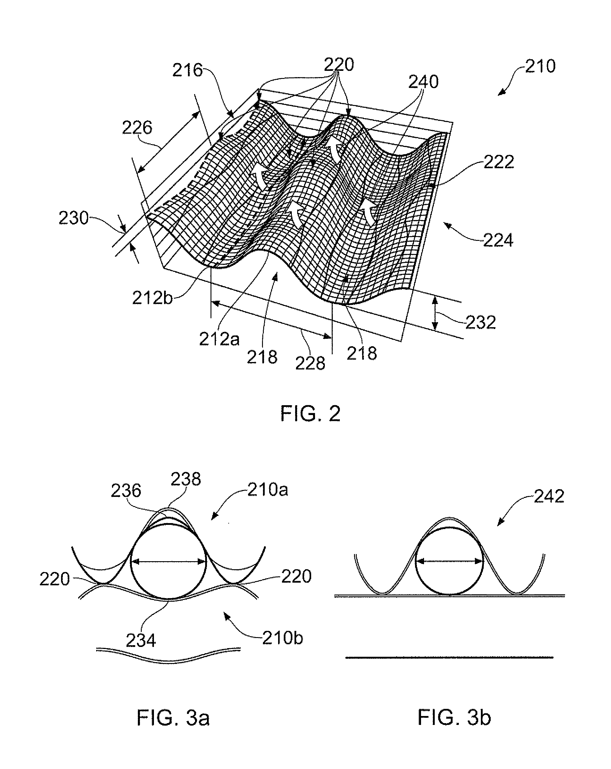
[0037]A further consideration of heat exchangers for aero-engines is the minimum flow cross-section area dimension through the matrix. Typically, it can be necessary for 1 mm diameter particles to be able to pass through an aero engine h...


PUM


Abstract

This invention relates to a heat exchanger, comprising a plurality of stacked corrugated plates, each plate having a plurality of parallel main corrugations each having longitudinal peak ridges and trough ridges, wherein either or both of the peak ridges and trough ridges have an undulating profile so as to define a plurality of summits in a common plane.

Description

TECHNICAL FIELD OF INVENTION[0001]This invention relates to heat exchangers. In particular, the invention relates to cross-corrugated heat exchangers.BACKGROUND OF INVENTION[0002]The use of heat exchangers to transfer the thermal energy from a hot fluid to a cold fluid is well known and finds application in many different industries. One type of heat exchanger having good thermal and pneumatic performance is a cross-corrugated plate heat exchanger 10 as shown in FIG. 1.[0003]The cross corrugated plate heat exchanger 10 shown in FIG. 1 includes a number of corrugated plates 12 which are stacked on top of one another such that the channels formed 14 by the corrugations lie at an angle to one another (90 degrees in this case). The plates are joined together by any suitable application led manufacturing technique such as brazing or welding. The material will also be application led but will typically be aluminium or other metal with a high thermal conductivity.[0004]Although not shown f...

Claims


Application Information

Patent Timeline
IPC IPC(8): F28F3/00
CPCF28F3/046F28F2250/106F28F3/005F28D9/0037
Inventor ROLT, ANDREW MARTINSTIEGER, RORY DOUGLAS
Owner ROLLS ROYCE PLC
Why Eureka
Try Eureka