Shield Apparatus for Use in Circuit Interrupter

a shield apparatus and circuit interrupter technology, applied in the direction of circuit-breaking switch details, electrical apparatus, electric switches, etc., can solve the problems of affecting the mechanical operation of the circuit interrupter

Inactive Publication Date: 2013-06-20
EATON CORP
View PDF2 Cites 1 Cited by
  • Summary
  • Abstract
  • Description
  • Claims
  • Application Information

AI Technical Summary

Benefits of technology

[0006]An improved shield apparatus is structured to resist contamination due to an electrical arc event of an open region that is formed within an interior of a circuit interrupter. The open region is one within which a coil spring is movably disposed. The improved shield apparatus is formed of a flexible sheet of arc-resistant material and includes a support apparatus having an elongated leg, at least a portion of which extends through an elongated longitudinal opening in the coil spring and connects with an end of the coil spring. The shield apparatus further includes a shield element that is situated on an exterior surface of the coil spring and is structured to overlie at least a portion of an opening into the open region.
[0007]Accordingly, an aspect of the disclosed and claimed concept is to provide an improved shield apparatus that resists contamination due to an electrical arc event of an open region that is formed in a portion of an interior of a circuit interrupter.
[0008]Another aspect of the disclosed and claimed concept is to provide such an improved shield apparatus that is mounted on a coil spring of a circuit interrupter and that is movable with the coil spring when the circuit interrupter moves between an ON condition and an OFF condition.
[0009]Another aspect of the disclosed and claimed concept is to provide such an improved shield apparatus having an elongated leg, at least a portion of which is structured to extend through an elongated longitudinal opening in the coil spring.
[0010]These and other aspects of the disclosed and claimed concept are provided by an improved shield apparatus that is structured to resist contamination due to an electrical arc event of an open region that is formed in a portion of a circuit interrupter and within which a coil spring is movably disposed. The shield apparatus can be generally stated as including a support apparatus and a shield element. The support apparatus can be generally stated as including a first support portion having an elongated leg, at least a portion of the leg being structured to extend through an elongated longitudinal opening in the coil spring. The shield element is disposed on the support apparatus and is structured to overlie at least a portion of the coil spring and at least a portion of an opening into the open region.

Problems solved by technology

However, at the moment of separation of the separable contacts, an electrical arc sometimes forms between the contacts, and any such arc is desirably extinguished as soon as possible due to the potential for damage to the circuit interrupter.
For instance, an arc between the separable contacts has a tendency to degrade the contact surfaces by vaporizing the metal of the contacts.
Moreover, such vaporized metal forms a plasma that can undesirably condense and become deposited on structures within the interior of the circuit interrupter.
Such deposits can interfere with the mechanical operations of the circuit interrupter and can have other undesirable effects.
While various devices and strategies for minimizing the effects of electrical arcs within the interiors of circuit interrupters have been implemented, limitations have existed.
For example, mechanical devices within the interior of a circuit interrupter that have a small physical clearance between them are particularly susceptible to fouling and obstructed operation when the plasma from an electrical arc is deposited in the vicinity of the small physical clearance.

Method used


Image

  • Shield Apparatus for Use in Circuit Interrupter
  • Shield Apparatus for Use in Circuit Interrupter
  • Shield Apparatus for Use in Circuit Interrupter

Examples


Embodiment Construction

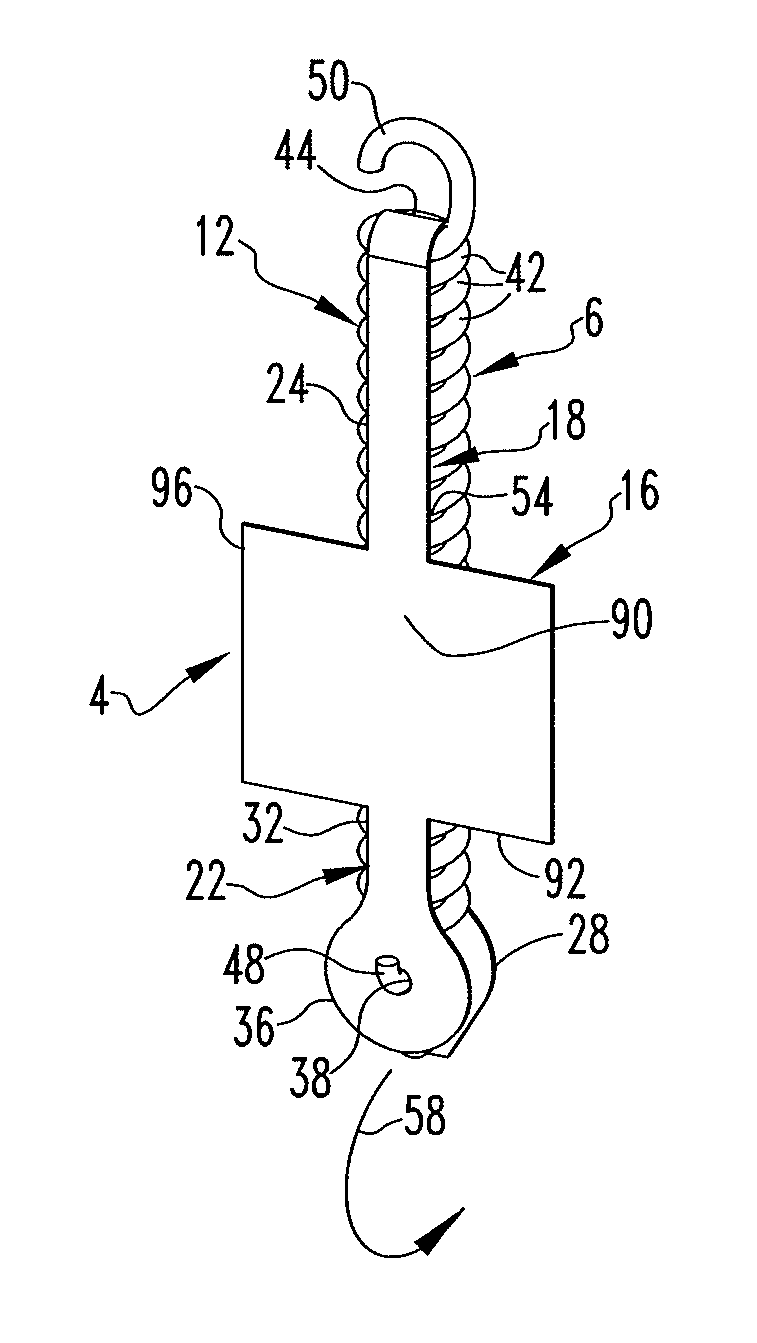
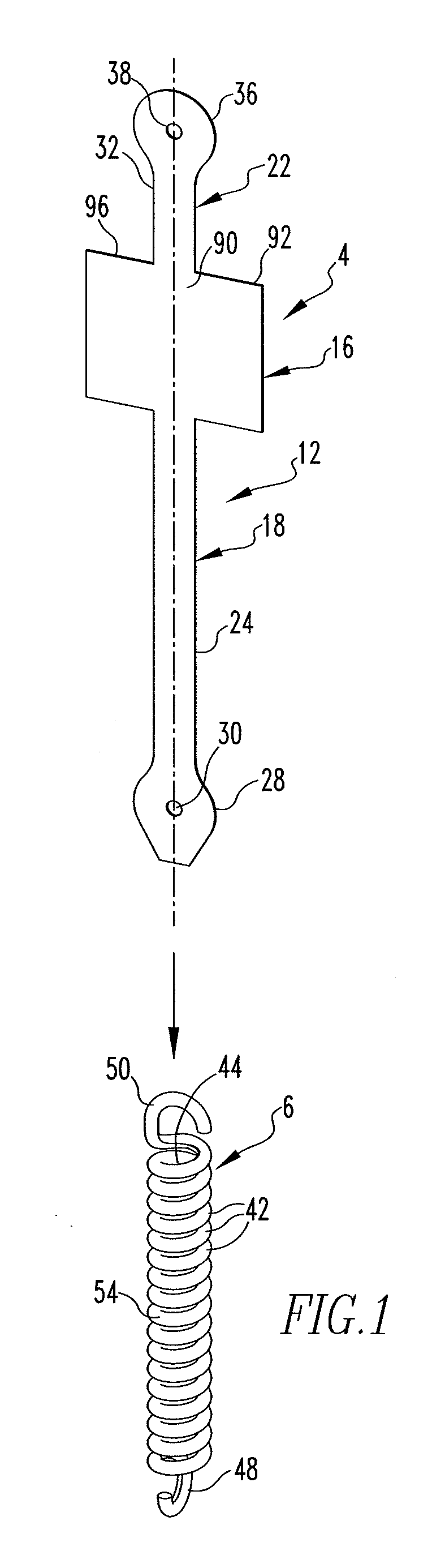
[0021]An improved shield apparatus 4 is depicted in FIG. 1 as being spaced from a coil spring 6 of a circuit interrupter 10, an example of which is depicted generally in FIGS. 4-5. As will be discussed in greater detail below, the circuit interrupter 10 has an open region formed therein, and the shield apparatus 4 is advantageously mounted on the coil spring 6 and is movable with the coil spring 6 to resist contamination of the coil spring 6 and the open region of the circuit interrupter 10 within which the coil spring 6 is movably disposed

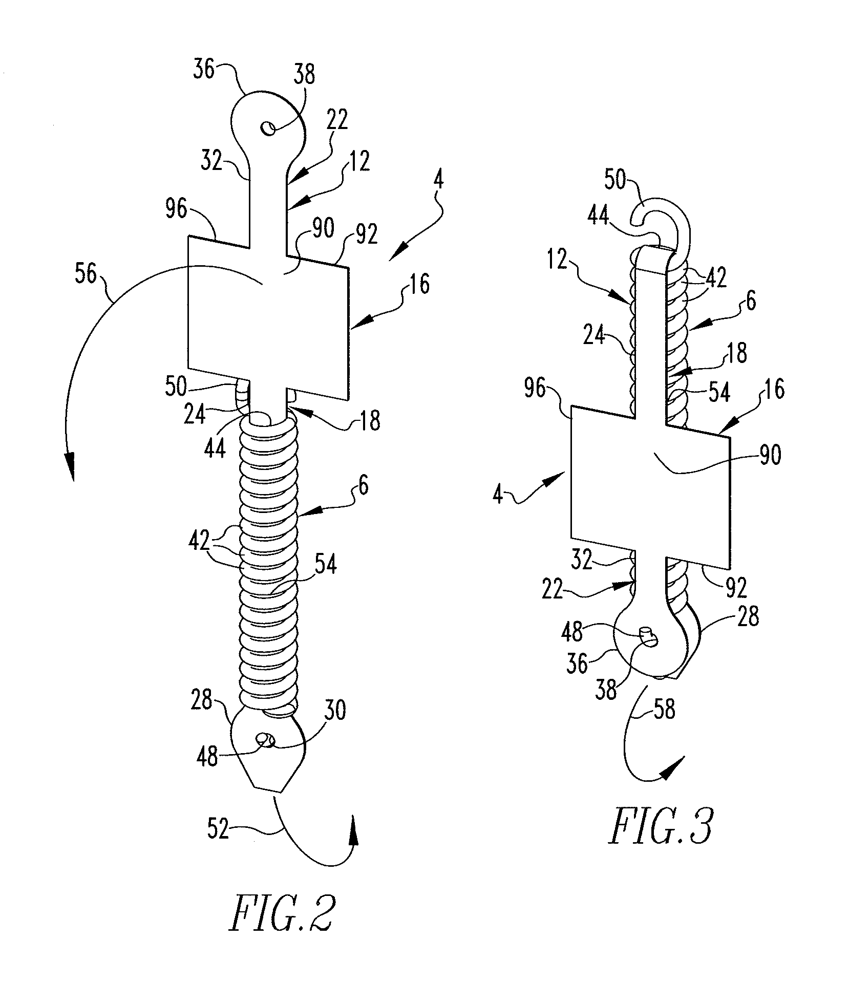
[0022]The shield apparatus 4 can be said to include a support apparatus 12 and a shield element 16, with the shield element 16 being disposed on the support apparatus 12. The support apparatus 12 can be said to include a first support portion 18 and a second support portion 22 that are connected with the shield element 16 and that extend in opposite directions away from the shield element 16.

[0023]As is best shown in FIGS. 1 and 2, the first suppo...


PUM


Abstract

An improved shield apparatus is structured to resist contamination due to an electrical arc event of an open region that is formed within an interior of a circuit interrupter. The open region is one within which a coil spring is movably disposed. The improved shield apparatus is formed of a flexible sheet of arc-resistant material and includes a support apparatus having an elongated leg, at least a portion of which extends through an elongated longitudinal opening in the coil spring and connects with an end of the coil spring. The shield apparatus further includes a shield element that is situated on an exterior surface of the coil spring and is structured to overlie at least a portion of an opening into the open region.

Description

BACKGROUND OF THE INVENTION[0001]1. Field of the Invention[0002]The disclosed and claimed concept relates generally to circuit interrupters and, more specifically, to a shield apparatus that is structured to resist contamination due to an electrical arc event of an open region within a circuit interrupter.[0003]2. Background Information[0004]Circuit interrupters are employed in numerous applications. As is generally understood, circuit interrupters typically include a set of separable contacts which, when separated, interrupt current flowing through a circuit. However, at the moment of separation of the separable contacts, an electrical arc sometimes forms between the contacts, and any such arc is desirably extinguished as soon as possible due to the potential for damage to the circuit interrupter.[0005]For instance, an arc between the separable contacts has a tendency to degrade the contact surfaces by vaporizing the metal of the contacts. Moreover, such vaporized metal forms a pla...

Claims


Application Information

Patent Timeline
Patent Type & Authority Applications(United States)
IPC IPC(8): H01H9/00
CPCH01H2009/305H01H73/18
Inventor MALONEY, JAMES GERARDLOCKHART, JEFFREY WAYNE
Owner EATON CORP
Why Eureka
Try Eureka