Packaging For The Storage, Protection And Transport Of Syringes
a technology for packaging and syringes, applied in the field of packaging units for the storage, protection and transportation of containers, can solve the problems of not being able to maintain syringes throughout the production chain, not being able to automatically process devices, and being unable to meet the needs of storing syringes, so as to prevent the risk of creation and facilitate handling
- Summary
- Abstract
- Description
- Claims
- Application Information
AI Technical Summary
Benefits of technology
Problems solved by technology
Method used
Image

Examples
first embodiment
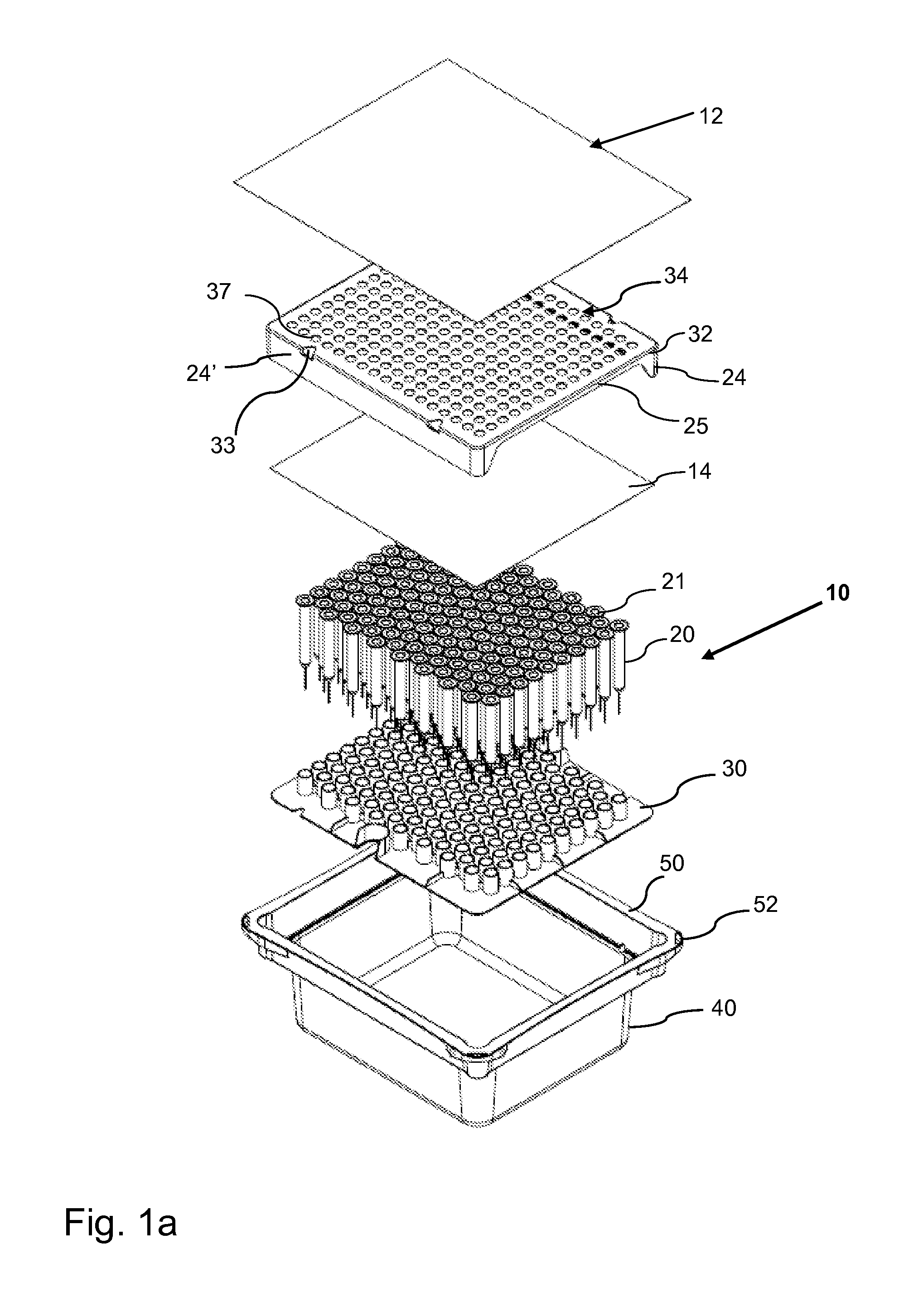
[0052]FIG. 1a is a view in exploded perspective of components of a packaging unit 10 according to the invention, and represents in succession, from top to bottom, a cap 12 which can be used to close the packaging unit, a cover 32, an optional separation sheet 14, an assembly of syringes 20 with flanges 21, a nest tray 30 and a box 40.
[0053]According to the invention, the cover 32 has an upper wall 34, and flanks 24, 24′ which extend downwards from two opposite sides of the upper wall 34. The tray represented in the following examples is a nest tray. The invention can however also be used in conjunction with a comb tray. Hereinafter, the generic term “tray” will be used to designate these two types of trays.
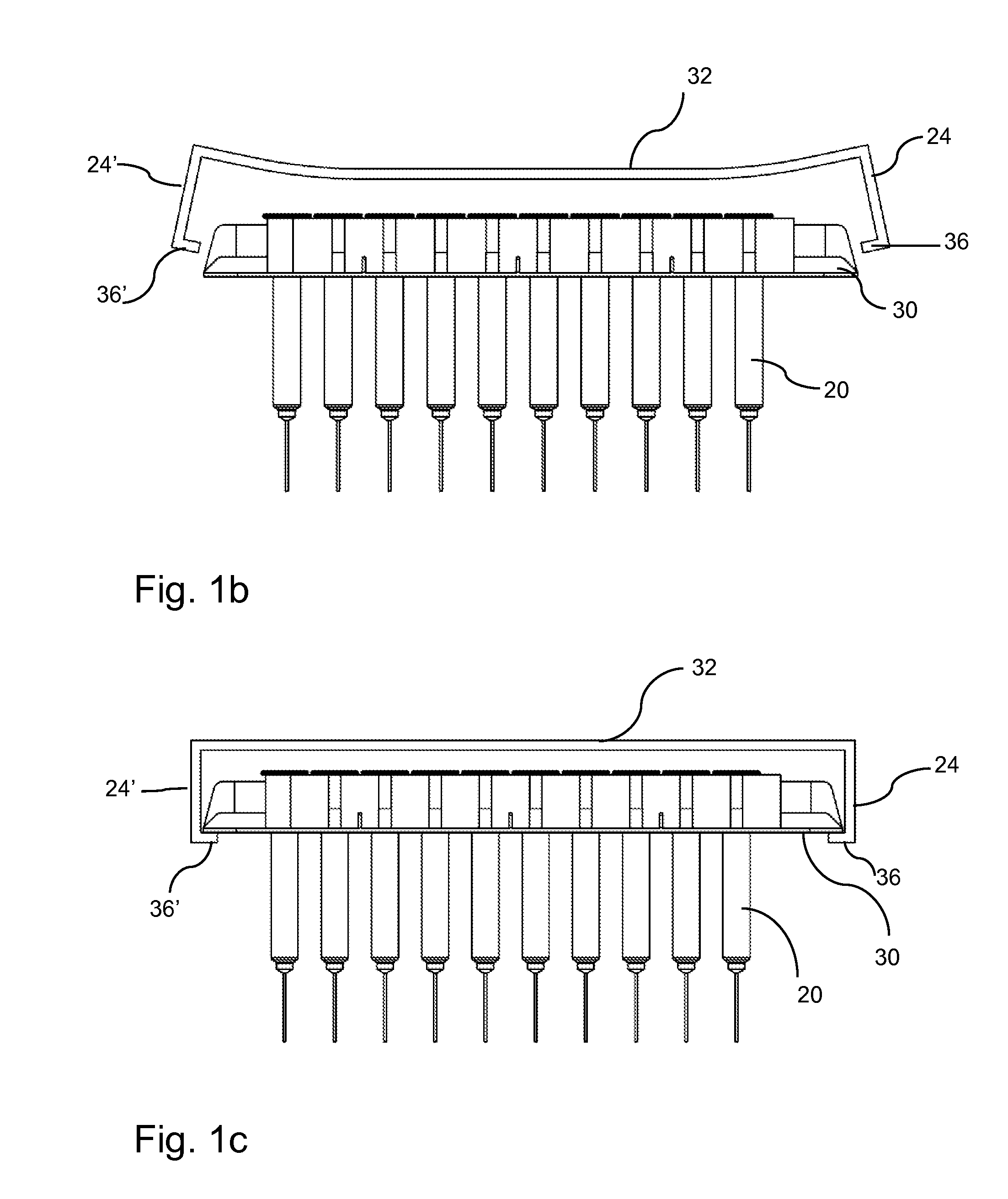
[0054]FIGS. 1b and 1c represent a method for rendering the cover 32 integral with a tray 30. The assembly of a cover 32 on a tray 30 and removal from it can be carried out very easily by automatic means: for example, a grasping tool of a robot comprises a plurality of suckers whic...
second embodiment
[0058]According to the invention, represented in FIG. 2e, the cover 32 additionally comprises support walls 26, 26′ which are parallel to the flanks 24, 24′, and are situated on the inner side of the latter. These support walls 26, 26′ constitute a bearing for the cover 32 on the periphery of the tray 30. They have a height such that neither the upper wall 34 nor the ribs 35 are supported on the upper surface of the flanges 21 of the containers 20. It is thus possible to stack a number of packaging units 10, without risk of applying forces on the containers 20.
[0059]FIG. 3a is a view in perspective and in cross-section of a packaging unit comprising a cover 32 according to a third embodiment of the invention. According to this mode, the flanks 24, 24′ on two sides of the cover 32 are interrupted and placed at portions of tube 60. These portions of tube play the part of the support walls 26, 26′ of the second embodiment: they permit the support of the cover 32 on the tray 30. An adva...
third embodiment
[0060]FIG. 3b is a view from below of a cover 32 according to the Portions of tube 62 are also provided on the two other sides of the cover 32, which has the effect of facilitating the bending of the cover, despite the presence of flanks 25, 25′ on these sides. The fingers 36, 36′ are arranged at the level of the tubes of the portions of tube 60, 60′, thus permitting creation of a mold which is simple to produce.
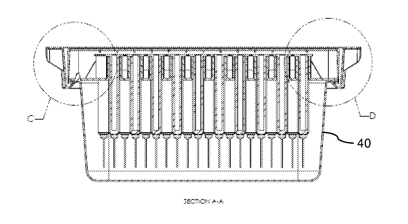
[0061]FIG. 4a is a plan view of a box 40 containing a tray 30 of a packaging unit according to the invention, and shows the position of the means for immobilization of the tray 30 in the box 40. According to first means for immobilization, represented in FIGS. 4a and 4b, centering pins 46, 46′ are provided on the step 45 of the box, and corresponding immobilization cut-outs 47, 47′ are provided in the tray 30.
[0062]FIG. 2c is an enlarged view of the cross-section A-A which shows the centering pin 46. This FIG. 2c shows that this centering pin has a frustoconical form. In ad...
PUM
 Abstract
Description
Claims
Application Information
 - R&D
- Intellectual Property
- Life Sciences
- Materials
- Tech Scout
- Unparalleled Data Quality
- Higher Quality Content
- 60% Fewer Hallucinations
Browse by: Latest US Patents, China's latest patents, Technical Efficacy Thesaurus, Application Domain, Technology Topic, Popular Technical Reports.
© 2025 PatSnap. All rights reserved.Legal|Privacy policy|Modern Slavery Act Transparency Statement|Sitemap|About US| Contact US: help@patsnap.com