Method for manufacturing stator, apparatus for manufacturing stator, and stator

a manufacturing method and stator technology, applied in the direction of metal working apparatus, manufacturing tools, windings, etc., can solve the problems of reducing the manufacturing efficiency of stators, difficult task for arranging pins on insulators, and complicated movement of nozzles

Inactive Publication Date: 2013-06-27
ASMO CO LTD
View PDF3 Cites 35 Cited by
  • Summary
  • Abstract
  • Description
  • Claims
  • Application Information

AI Technical Summary

Problems solved by technology

However, when the lead lines are connected to the substrate by implementing the method described in the above publication, the task for arran...

Method used


Image

  • Method for manufacturing stator, apparatus for manufacturing stator, and stator
  • Method for manufacturing stator, apparatus for manufacturing stator, and stator
  • Method for manufacturing stator, apparatus for manufacturing stator, and stator

Examples


Embodiment Construction

[0026]One embodiment of the present invention will now be described with reference to the drawings.

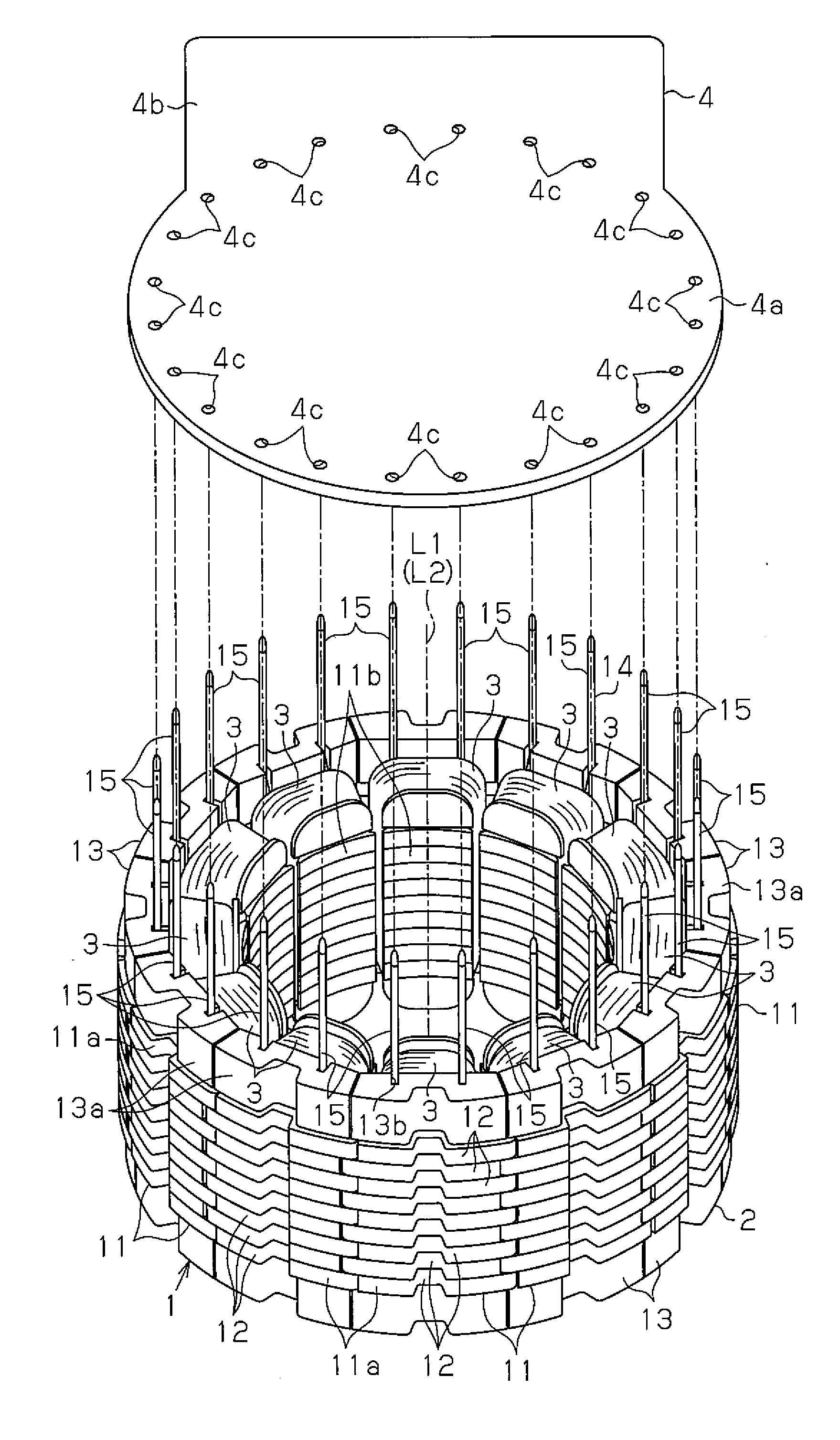
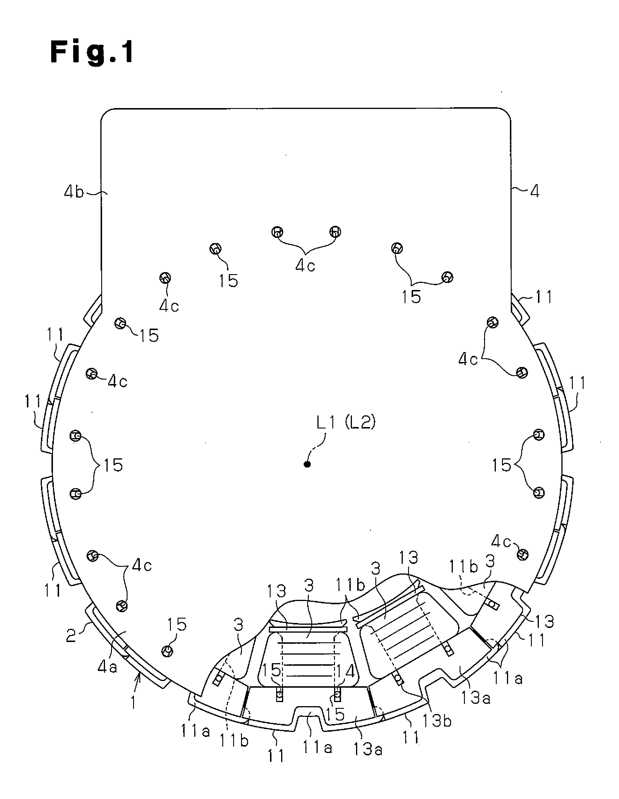
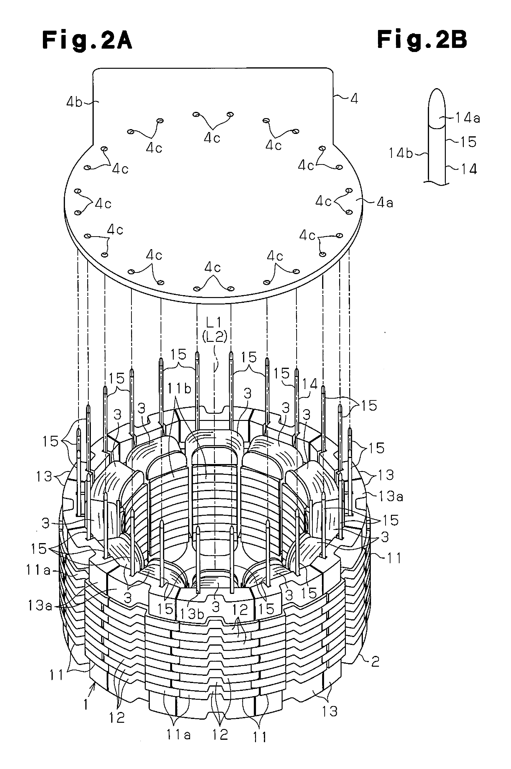
[0027]FIG. 1 shows a stator 1 arranged in an inner rotor brushless motor. The stator 1 includes a stator core 2 having an annular shape, a plurality of coils 3 (12 coils) wound around the stator core 2, and a substrate 4 to which the coils 3 are electrically connected.

[0028]As illustrated in FIGS. 1 and 2A, the stator core 2 is annular and includes twelve core segments 11, which are T-shaped as viewed from an axial direction and circumferentially coupled with one another. The core segments 11 each include a coupling portion 11a having an arc shape when viewed from the axial direction and a tooth 11b extending radially inward from a circumferentially central part of the coupling portion 11a. Describing the structure of the core segment 11, a plurality of core sheets 12, each formed by pressing and punching a magnetic steel plate into a predetermined shape are stacked so that a thickness...


PUM

PropertyMeasurementUnit
Thicknessaaaaaaaaaa
Lengthaaaaaaaaaa
Widthaaaaaaaaaa

Abstract

A method for manufacturing a stator includes preparing a stator core having a plurality of teeth, a plurality of coils having a plurality of lead lines, a substrate having a plurality of connecting portions, and a plurality of positioning jigs having restraining portions. The method includes positioning the substrate and the lead lines so that distal portions of the lead lines are separated from the connecting portions in at least one of a radial direction and a circumferential direction. The method further includes inserting the lead lines in the restraining portions, aligning the distal portions of the lead lines with the corresponding connecting portions using the positioning jigs, inserting the lead lines into the corresponding connecting portions, and electrically connecting the lead lines inserted in the connecting portions to the corresponding connecting portions.

Description

BACKGROUND OF THE PRESENT INVENTION[0001]The present invention relates to a method for manufacturing a stator including a substrate for connection to coils, an apparatus for manufacturing a stator, and a stator.[0002]A conventional motor includes coils wound around an annular stator core. Each coil includes a winding-initiating ends and winding-terminating end that form lead lines, which are drawn out from one axial end of the stator core. The lead lines are electrically connected to, for example, a substrate arranged on one axial side of the stator core. The substrate electrically connects predetermined ones of the coils. Further, the coils are supplied with excitation current through the substrate.[0003]Japanese Laid-Open Patent Publication No. 06-233505 describes an example of a method for manufacturing such a stator including a substrate. The method uses L-shaped pins to connect lead lines of coils to a substrate arranged at one axial side of the stator core. The stator core inc...

Claims


Application Information

Patent Timeline
IPC IPC(8): H02K15/06H02K3/34H02K3/50
CPCH02K3/522H02K15/0075H02K2203/03Y10T29/49009H02K3/50H02K15/065Y10T29/53143H02K3/345H02K15/0068
Inventor MIZUTANI, HIROYUKINAKAGAWA, YOSHITSUGUISHINO, YUKIHIDE
Owner ASMO CO LTD
Why Eureka
Try Eureka