
Precharge circuit and non-volatile memory device

a non-volatile memory and circuit technology, applied in the field of pre-charge circuits, can solve the problems of power drop, the level difference dv between the positive the negative local input/output line liob may not be adequate to ensure a stable sensing operation

Active Publication Date: 2013-06-27
SK HYNIX INC
View PDF4 Cites 370 Cited by
  • Summary
  • Abstract
  • Description
  • Claims
  • Application Information

AI Technical Summary

Benefits of technology

The present invention is about a circuit that controls a precharge operation by sensing a change in voltage. A precharge circuit includes a unit that applies a voltage to a data line and a sensing unit that disables the precharge unit when the voltage level exceeds a certain threshold. A non-volatile memory device includes an access unit, a data line, a precharge unit, and a sensing unit. The technical effect of this invention is to improve the speed and reliability of memory accesses by controlling the precharge operation.

Problems solved by technology

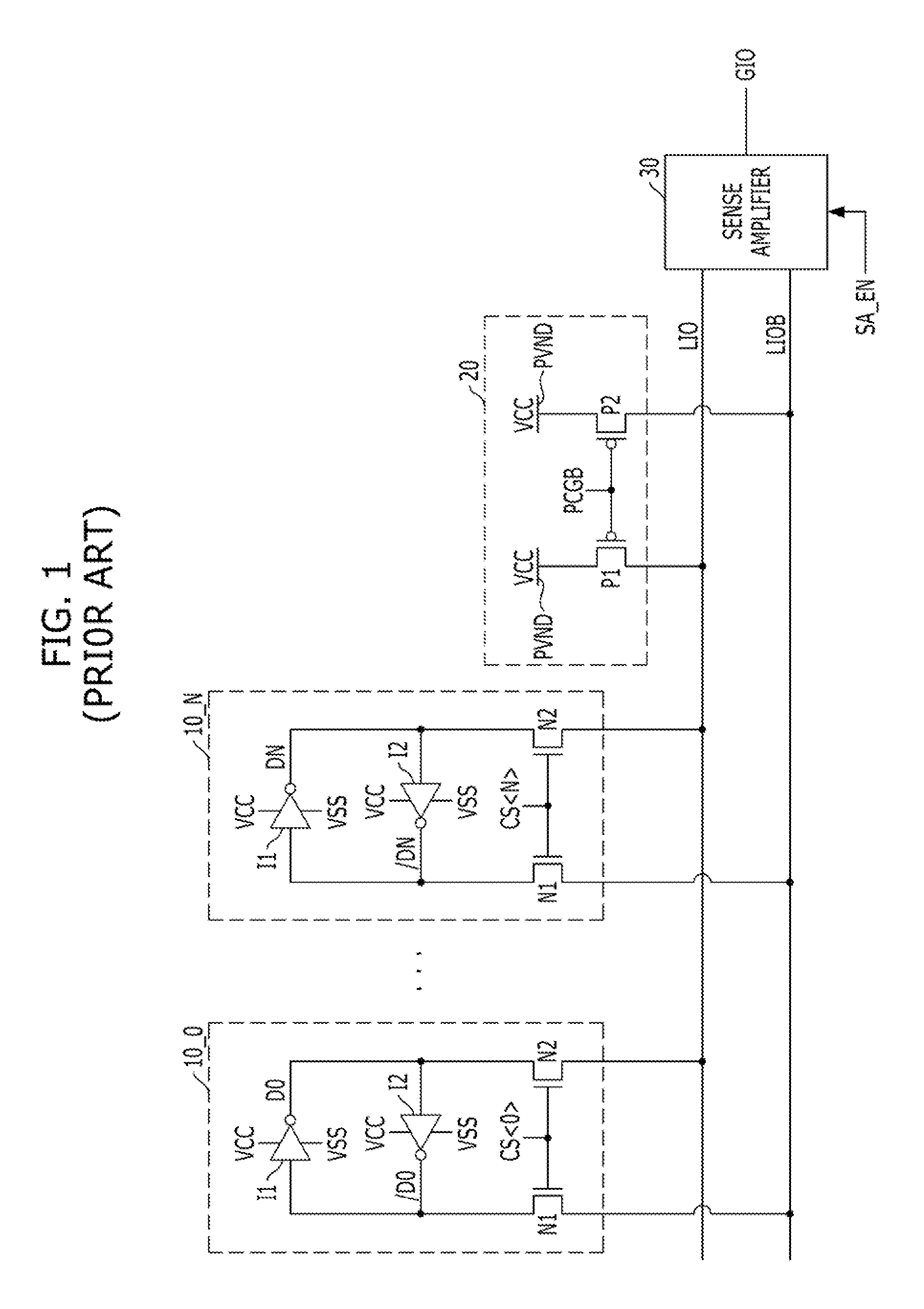
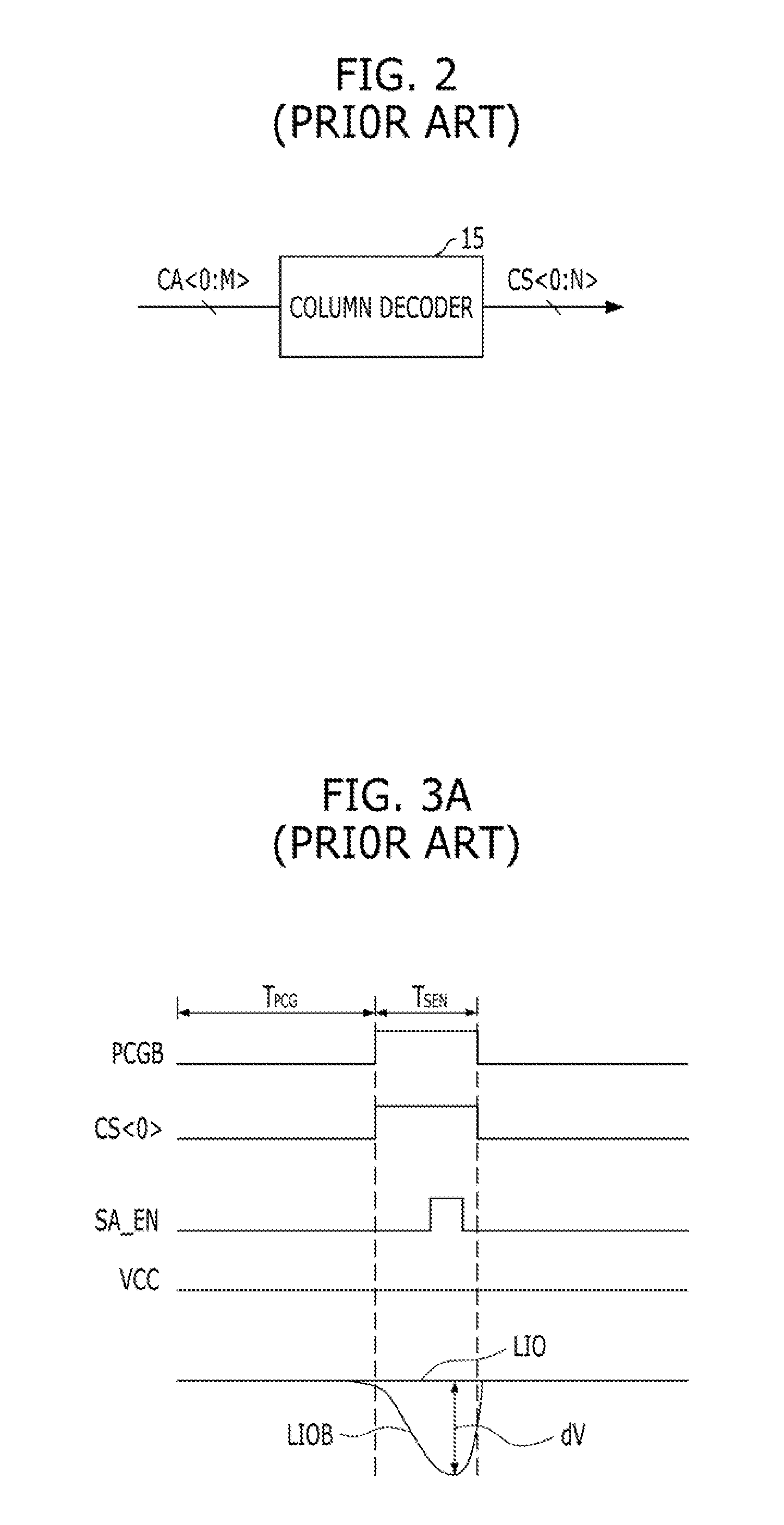
Meanwhile, if the voltage level VCC of the precharge voltage terminal PVND is not maintained at a constant level, it is not sure whether the sensing operation is performed accurately, In particular, since the non-volatile memory device simultaneously accesses the data of the memory cell array (not shown) on the basis of a page by using the multiple page buffers 10_0 to 10_N, it consumes much current and this leads to a power drop, If the voltage level of the precharge voltage terminal PVND of the precharger 20 drops due to the simultaneous access of the page buffers 10_0 to 10_N to the data of the memory cell array (not shown), the voltage level difference dV between the positive local input / output line LIO and the negative local input / output line LIOB may not be adequate for making sure a stable sensing operation.

Method used


Image

  • Precharge circuit and non-volatile memory device
  • Precharge circuit and non-volatile memory device
  • Precharge circuit and non-volatile memory device

Examples


Embodiment Construction

[0030]Exemplary embodiments of the present invention will be described below in more detail with reference to the accompanying drawings. The present invention may, however, be embodied in different forms and should not be construed as limited to the embodiments set forth herein, Rather, these embodiments are provided so that this disclosure will be thorough and complete, and will fully convey the scope of the present invention to those skilled in the art. Throughout the disclosure, like reference numerals refer to like parts throughout the various figures and embodiments of the present invention.

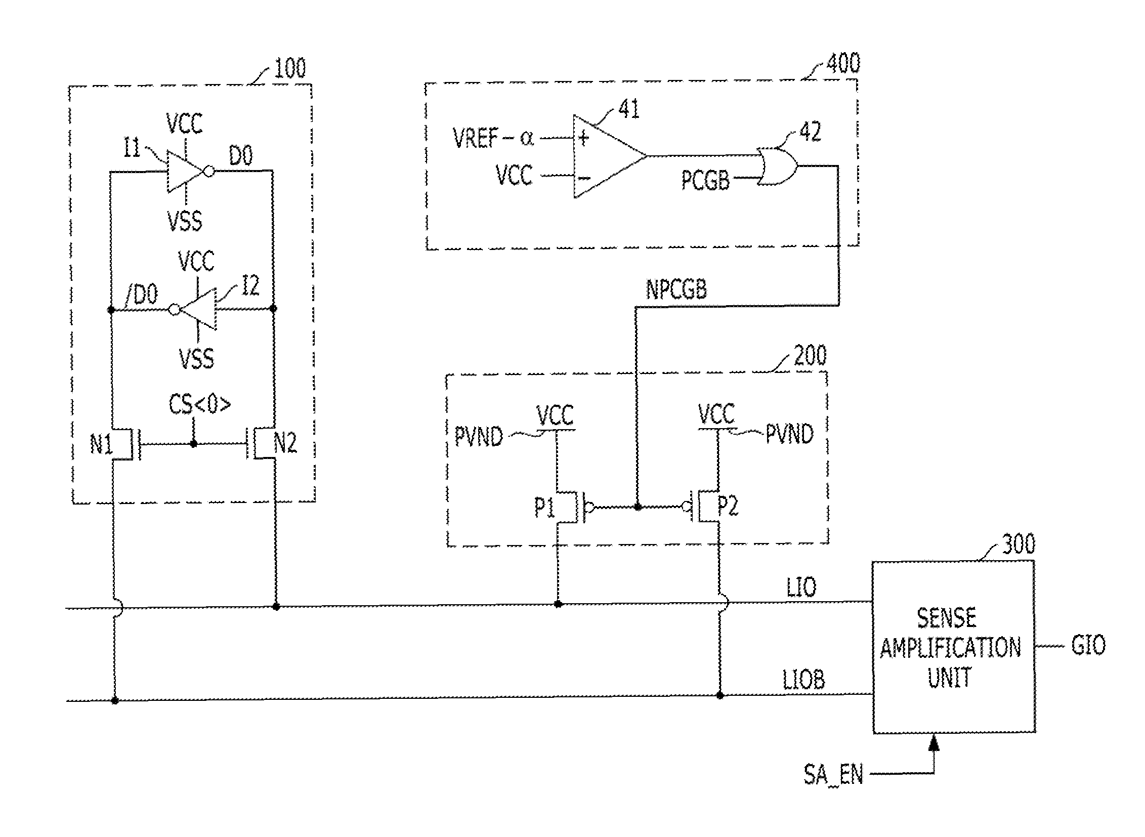
[0031]FIG. 4 is a schematic diagram illustrating a non-volatile memory device in accordance with an exemplary embodiment of the present invention.

[0032]The non-volatile memory device may include an access unit 100, data lines LIO and LIOB, a precharge unit 200, a sensing unit 400, and a sense amplification unit 300.

[0033]The access unit 100 accesses a data D0 stored in a memory cell (not sho...


PUM


Abstract

A precharge circuit includes a precharge unit configured to apply a voltage of a precharge voltage terminal to a data line during a precharge operation, and a sensing unit configured to disable the precharge unit by sensing the voltage of the precharge voltage terminal, The precharge circuit may control a precharge operation by sensing a change in the voltage level of the precharge voltage terminal.

Description

CROSS-REFERENCE TO RELATED APPLICATIONS[0001]The present application claims priority of Korean Patent Application No. 10-2011-0140480 filed on Dec 22, 2011, which is incorporated herein by reference in its entirety.BACKGROUND[0002]1. Field[0003]Exemplary embodiments of the present invention relate to a precharge circuit for supplying a precharge voltage to a data line.[0004]2. Description of the Related Art[0005]An integrated circuit chip that inputs / outputs data through a data line uses a precharge circuit in order to precharge the data line for the next operation after completing a data input operation or a data output operation,[0006]FIG. 1 is a schematic diagram illustrating a conventional non-volatile memory device including a precharge circuit. The conventional non-volatile memory device shown in FIG. 1 includes a plurality of page buffers 10_0 to 10_N, a precharger 20, and a sense amplifier 30.[0007]The precharger 20 applies the voltage of a precharge voltage terminal PVND to...

Claims


Application Information

Patent Timeline
IPC IPC(8): G11C7/00
CPCG11C7/00G11C7/12G11C7/08G11C16/06G11C16/30
Inventor KIM, SANG-HWAN
Owner SK HYNIX INC
Learn More