Floating treatment streambed

a technology of floating treatment and streambed, which is applied in the field of water treatment, can solve the problems of limiting the species of fish, the majority of the water volume in these bodies cannot support fish life, and the inability to provide habitat for fish and other aquatic wildlife species,

Active Publication Date: 2013-07-04
FOUNTAINHEAD
View PDF10 Cites 5 Cited by
  • Summary
  • Abstract
  • Description
  • Claims
  • Application Information

AI Technical Summary

Benefits of technology

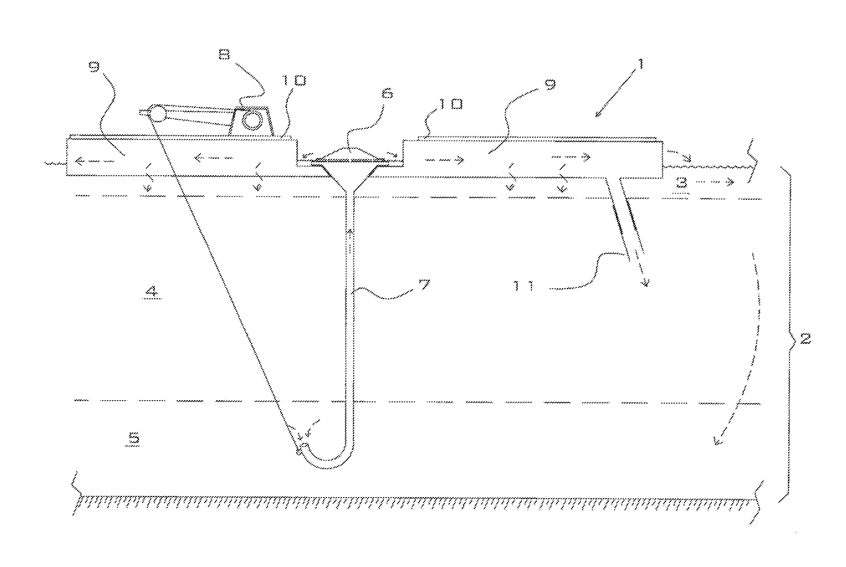
This patent describes a method for improving water environments by creating deeper, oxygen-rich zones and cooler shallow zones, reducing the growth of algae and other plants, and promoting the growth of fish and other wildlife. The method combines water circulation and bioremediation to mitigate oxygen-deficiency and eutrification issues. The method can be adjusted for different sites to create optimal remediation conditions.

Problems solved by technology

Many lakes and ponds contain stratified layers of water, in which the cooler lower levels are often deficient in dissolved oxygen and, therefore, unable to provide habitat for fish and other aquatic wildlife species.
), which thrive in the relatively sunlit and nutrient-rich upper zones, then die and fall to the bottom, where their decay contributes to the oxygen deficiency problem in the deeper zones.
Not uncommonly, the majority of the water volume in these bodies is unable to support fish life because the upper layers are deficient in dissolved oxygen due to elevated water temperatures, and the lower layers are simultaneously deficient in dissolved oxygen due to lack of circulation.
Water temperature in combination with dissolved oxygen level can also limit which species of fish may occur in a waterway.
In addition to reduced fish sustainability, these stratified waters also have reduced potential for municipal, agricultural, and recreational use because of the presence of toxins and suspended solids resulting from poor circulation and lack of microbiological activity.

Method used


Image

  • Floating treatment streambed
  • Floating treatment streambed
  • Floating treatment streambed

Examples


first embodiment

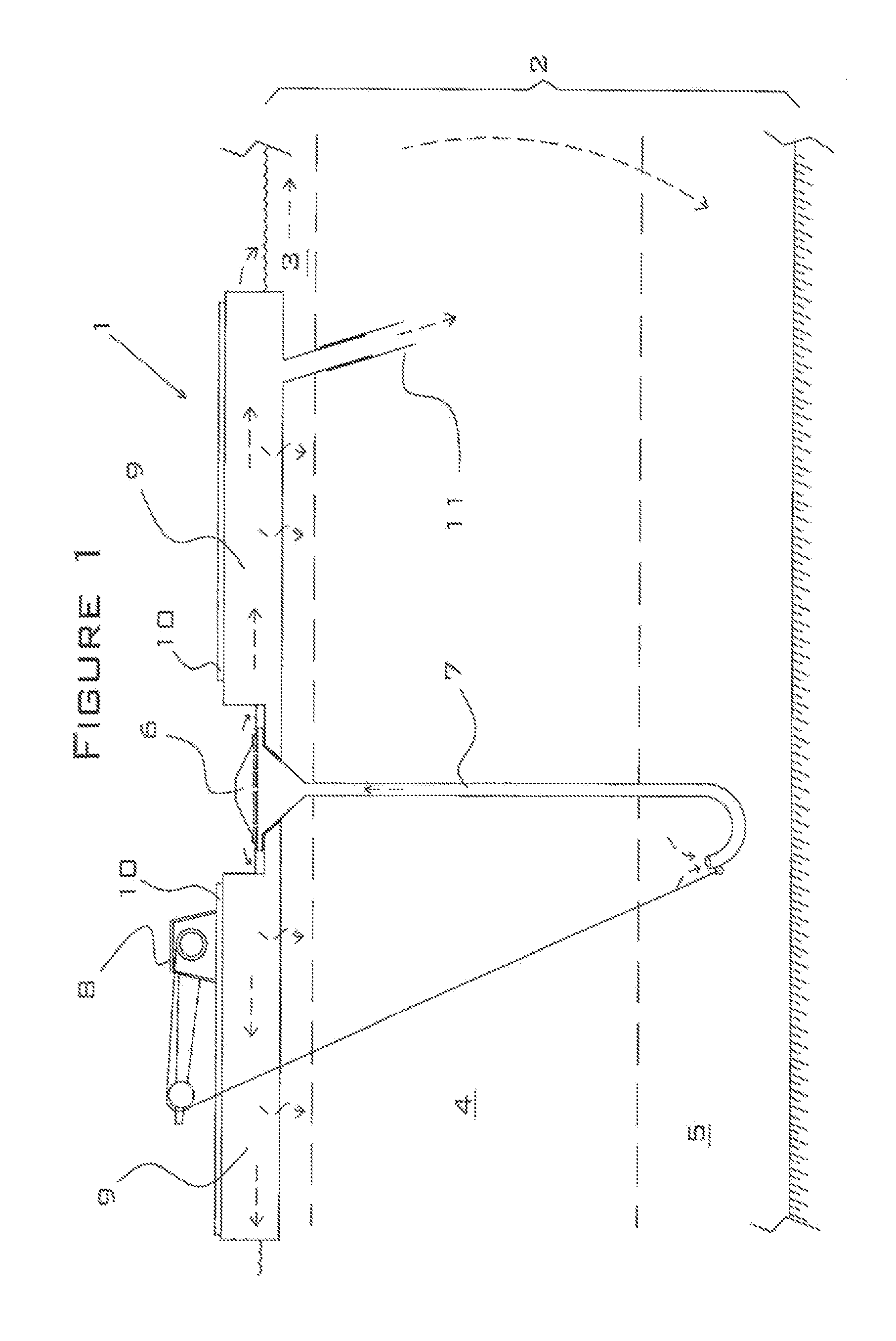
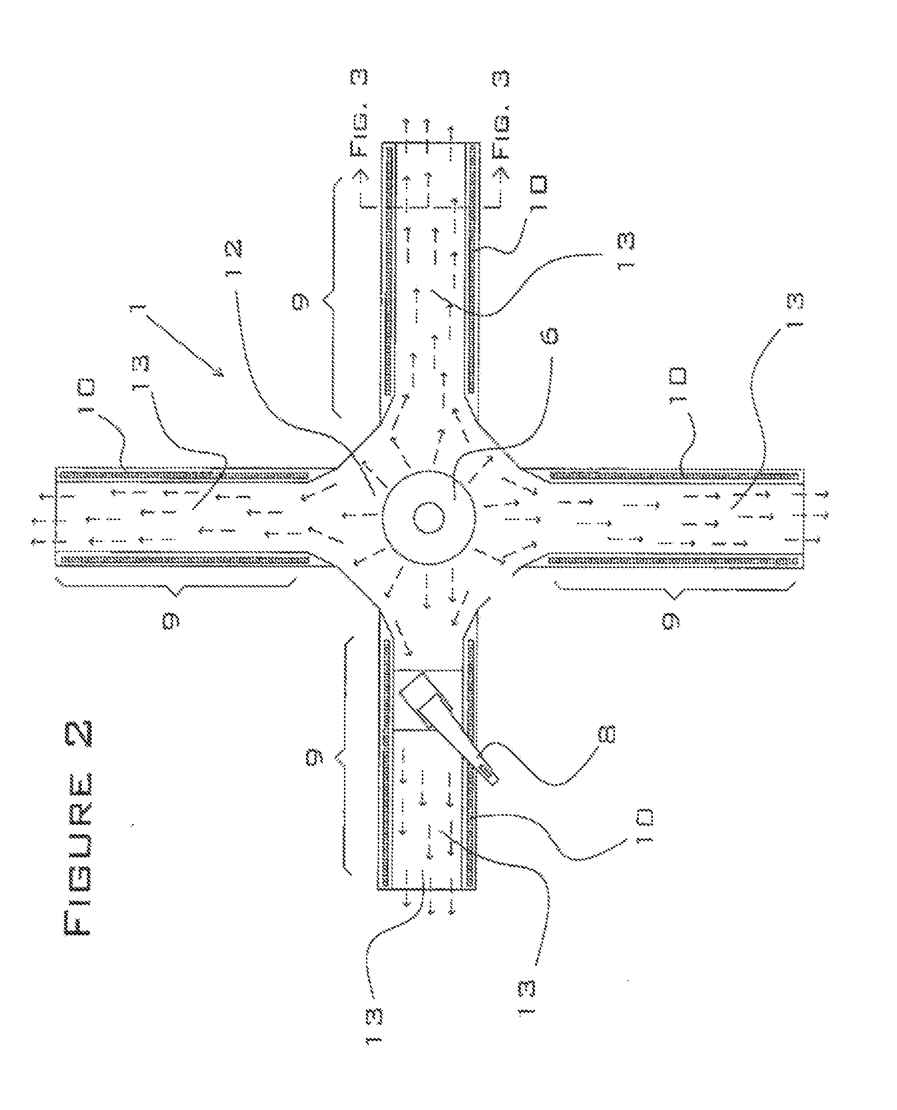
[0166]FIG. 3 is a schematic cross-section view of a treatment channel 9. In this embodiment, walkways 10 are positioned on either side of the treatment channel 9. This figure also shows the permeable matrix 14, the periphyton layer 15, the treatment water 13, and the flotation units 16. The treatment channel 9 is shown floating in stratified water body 2. The dashed arrows in FIG. 3 represent the portion of treatment water 13 that percolates through the periphyton layer 15 and the permeable matrix 14. Note that water may percolate downward through the bottom of the treatment channel and also horizontally through the sides of the treatment channel. The periphyton layer 15 grows naturally on the bottom and sides of each treatment channel under typical ambient pond conditions.

[0167]Periphyton is typically a mixture of algae, cyanobacteria, bacteria, and their residue and detritus. Because algae require sunlight to survive, the periphyton layer 15 will typically be restricted to the out...

second embodiment

[0175]FIG. 4 is a schematic cross-section view of a treatment channel 9, which incorporates an optional impermeable channel liner 18 and an optional top cover 19. With this embodiment, percolation of the treatment water 13 through the permeable matrix 14 is prevented. This embodiment is preferred for applications in which it is desirable to maximize the time that the treatment water remains within the channel for treatment or for applications in which the channel contains in-stream filters.

[0176]The impermeable channel liner 18 may be comprised of materials that are suitable for use as pond liners—for example, polyethylene, polyvinyl chloride, EDPM rubber, or polypropylene sheeting. The impermeable liner material is preferably resistant to degradation by ultraviolet sunlight and is resistant to punctures and tears. The top cover 19 may be comprised of gas-impermeable polymer sheeting to prevent the treatment water 13 from coming into contact with atmospheric oxygen (exclusion of oxy...

third embodiment

[0177]FIG. 5 is a schematic cross-section view of a treatment channel 9, which comprises aquatic plants 20 and riparian or terrestrial plants 21. (As shown in this figure, the plants may be located within the treatment channel itself or in the matrix 14 on either side of the treatment channel.) The plants may be used to increase the removal rate of excess nutrients from the treatment water 13 via phytoextraction. The plants 20, 21 may also contribute to the aesthetic appeal of the structure. Wetland sod 22 or bedding plants or plugs may be used to grow the aquatic plants 20. Wetland sod is typically comprised of aquatic and riparian plants that are rooted into coir or jute blankets. One supplier of wetland sod is Great Bear Restoration of Hamilton, Mont. If wetland sod is utilized, it may be attached to the treatment channel bottom. Grass sod, bedding plants and / or seeds may be used to grow the riparian or terrestrial plants 21. The bedding plants or plugs and seeds may optionally b...


PUM

PropertyMeasurementUnit
lengthsaaaaaaaaaa
cured densityaaaaaaaaaa
diameteraaaaaaaaaa

Abstract

A floating streambed comprising a circulation pump having an inlet hose or pipe, an inlet hose or pipe depth adjuster, and one or more treatment channels comprised of permeable matrix. The floating streambed floats on a water body. Water enters the inlet hose or pipe from the water body and is pumped by the circulation pump into the treatment channels. The treatment channels are comprised of permeable matrix, and water entering the treatment channels flows both horizontally through the treatment channel and into the water body and also vertically downward through the permeable matrix of the treatment channels.

Description

CROSS-REFERENCE TO RELATED APPLICATIONS[0001]This application is a continuation-in-part of U.S. patent application Ser. No. 12 / 940,111 filed on Nov. 5, 2010, which in turn claims priority under 35 U.S.C. §119(e) back to U.S. Patent Application No. 61 / 260,800 filed on Nov. 12, 2009.BACKGROUND OF THE INVENTION[0002]1. Field of the Invention[0003]The present invention relates generally to the field of water treatment, and more specifically, to a floating streambed that utilizes a permeable nonwoven matrix to accomplish filtration of treatment water and allows both inlet and discharge water depth to be adjusted.[0004]2. Description of the Related Art[0005]Many lakes and ponds contain stratified layers of water, in which the cooler lower levels are often deficient in dissolved oxygen and, therefore, unable to provide habitat for fish and other aquatic wildlife species. In some cases, these water bodies tend to contain excess dissolved nutrients, such as nitrogen and phosphorus, from eith...

Claims


Application Information

Patent Timeline
Patent Type & Authority Applications(United States)
IPC IPC(8): C02F1/00
CPCA01G31/02C02F1/283C02F3/06C02F3/105C02F1/001C02F7/00C02F2103/007C02F2203/008C02F3/327Y02W10/37Y02W10/10C02F3/32C02F1/74
Inventor KANIA, BRUCE G.STEWART, FRANK M.
Owner FOUNTAINHEAD
Why Eureka
Try Eureka