Energy Absorbing Bracket For A Seat Of A Vehicle

a technology for vehicle seats and brackets, which is applied in the direction of vehicle components, pedestrian/occupant safety arrangements, vehicle arrangements, etc., can solve the problems of increasing the cost of seat backs and the requirement that the backs made of polymeric materials meet the structural requirements

Active Publication Date: 2013-07-11
BASF SE
View PDF20 Cites 4 Cited by
  • Summary
  • Abstract
  • Description
  • Claims
  • Application Information

AI Technical Summary

Benefits of technology

[0007]A bracket is used to couple together a seating frame member and a back frame member of a seat. The seating frame member provides a surface to support an occupant within a vehicle. The back frame member extends away from the seating frame member. The bracket comprises a periphery and a central longitudinal axis dividing the bracket into a front portion and a rear portion. The front portion of the bracket defines a yield segment for plastically deforming when a force above a predetermined value is applied to the back frame member. Plastically deforming the yield segment reduces an impact force transferred from the seat to the occupant caused by the force above the predetermined value. The periphery of the rear portion of the bracket includes a first contact surface and a second contact surface spaced from the first contact surface. The first and second contact surfaces define a bracket notch. The first contact surface moves into contact with the second contact surface as the yield segment plastically deforms thereby restricting the plastic deformation of the yield segment. Restricting the plastic deformation of the yield segments restricts a rotation of the back frame member relative to the seating frame member to ensure the rotation of the back frame member does not exceed a maximum deformation angle.

Problems solved by technology

As a result, a cost to manufacture the seat back has increased.
However, the seat back made from the polymeric material must still meet the structural requirements for a crash event.

Method used


Image

  • Energy Absorbing Bracket For A Seat Of A Vehicle
  • Energy Absorbing Bracket For A Seat Of A Vehicle
  • Energy Absorbing Bracket For A Seat Of A Vehicle

Examples


Embodiment Construction

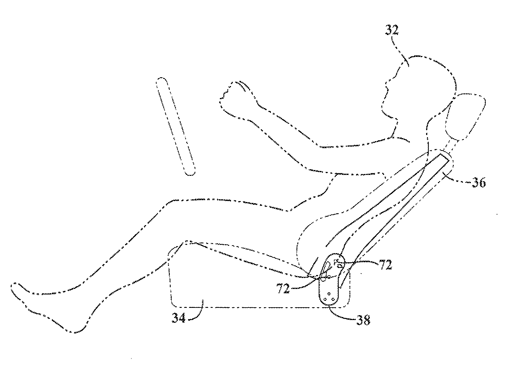
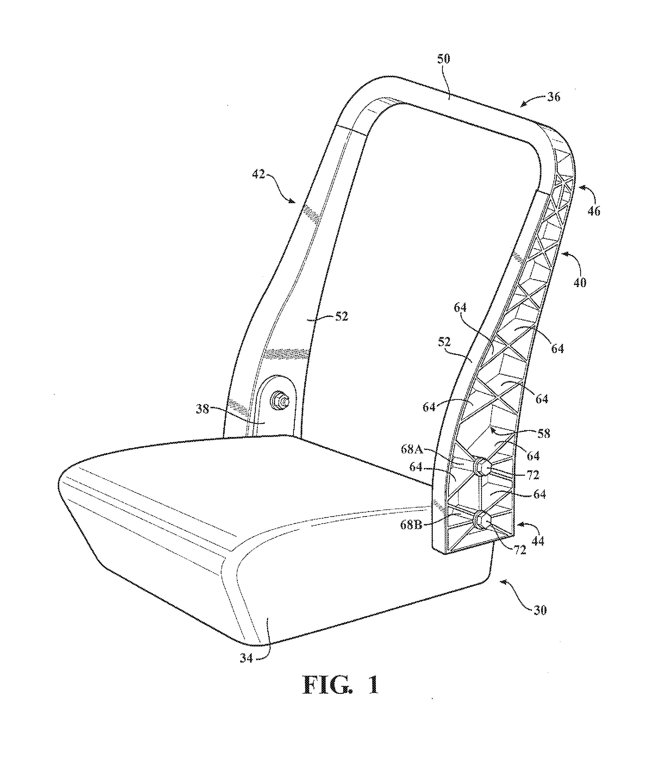
[0021]Referring to the Figures, wherein like numeral indicate like or corresponding parts throughout the several views, a seat 30 for a vehicle is generally shown. The seat 30 is coupled to the vehicle for supporting an occupant 32 in a standard position within the vehicle. With reference to FIG. 1, the seat 30 includes a seating frame member 34 extending generally horizontally and a back frame member 36 coupled to and extending away from the seating frame member 34.

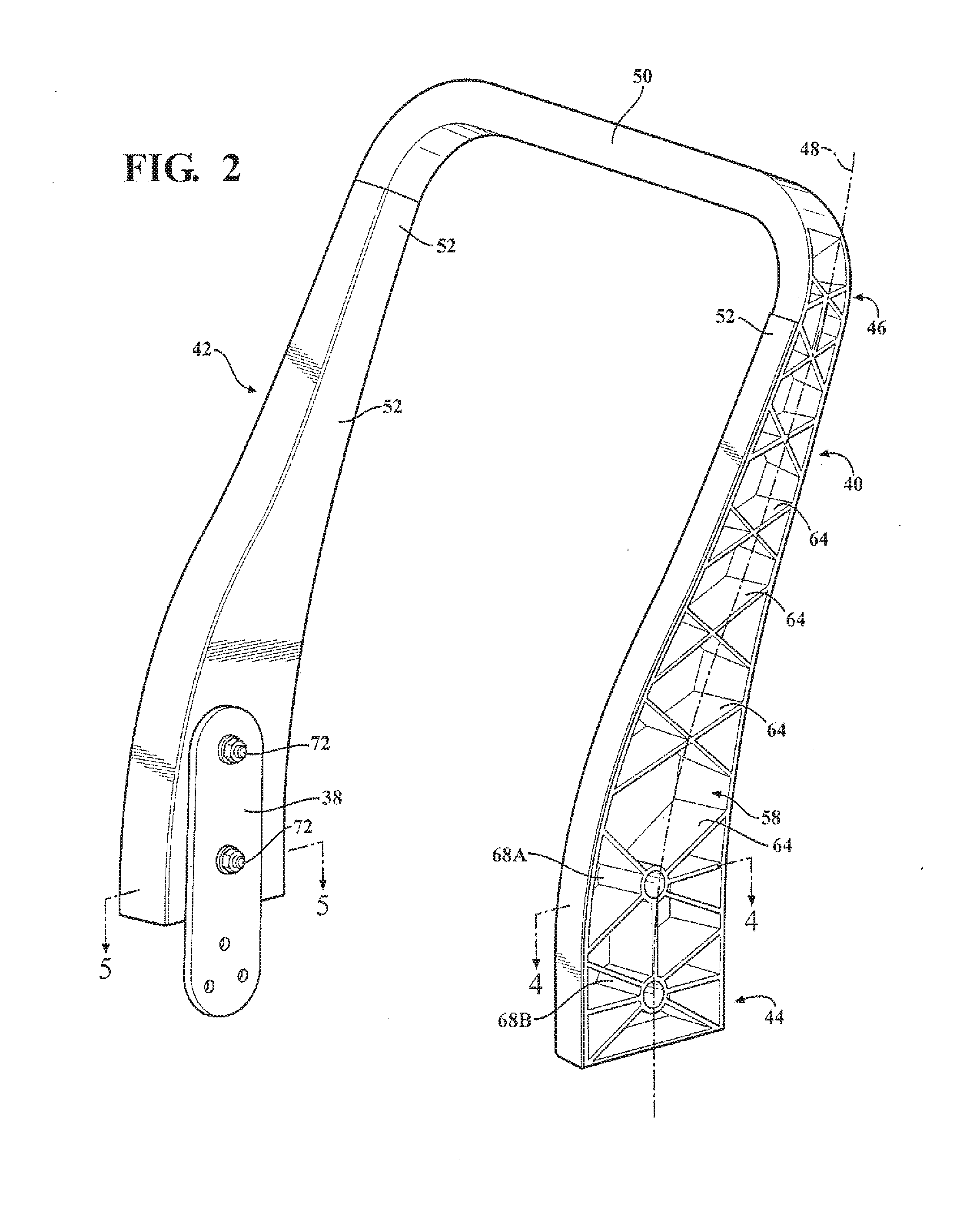
[0022]The back frame member 36 generally extends vertically away from the seating frame member 34. The back frame member 36 may include a first side member 40 and a second side member 42 each extending generally upwardly from the seating frame member 34. The side members 40, 42 each have a proximal end 44 proximate the seating frame member 34 and a distal end 46 spaced from the seating frame member 34. With reference to FIG. 2, each of the side members 40, 42 define a side member axis 48 extending from the proximal end 4...


PUM


Abstract

A bracket is used to couple together a seating frame member and a back frame member of a seat of a vehicle. The bracket comprises a periphery and a central longitudinal axis dividing the bracket into a front portion and a rear portion. The front portion of the bracket defines a yield segment for plastically deforming when a force above a predetermined value is applied to the back frame member. Plastically deforming the yield segment reduces an impact force transferred from the seat to an occupant. The periphery of the rear portion of the bracket includes a first contact surface and a second contact surface spaced from the first contact surface. The first contact surface moves into contact with the second contact surface as the yield segment plastically deforms thereby restricting the plastic deformation of the yield segment.

Description

CROSS REFERENCE TO RELATED APPLICATIONS[0001]This application claims the benefit of U.S. Provisional Patent Application Ser. No. 61 / 382,582 filed on Sep. 14, 2010 and incorporated herewith in its entirety.BACKGROUND OF THE INVENTION[0002]1. Field of the Invention[0003]The subject invention generally relates to a seat for a vehicle, and more specifically to the seat having at least one energy absorbing feature.[0004]2. Description of the Related Art[0005]Seats for a vehicle and specifically a back portion of the seat typically must meet structural requirements by having sufficient strength to support repeated loads, which are exerted on the back portion of the seat, or seat back, during a crash event. For example, when a vehicle is hit from behind by another vehicle, a mass of an occupant applies a large force on the seat back over a small time period. To meet these structural requirements, the seat back is generally formed from metal such as steel, aluminum, or magnesium. For exampl...

Claims


Application Information

Patent Timeline
Patent Type & Authority Applications(United States)
IPC IPC(8): B60N2/427
CPCB60N2/4228B60N2/42709B60N2/682B60N2/68B60N2/42745B60N2/42B60N2/427
Inventor EVANS, JONATHAN
Owner BASF SE
Why Eureka
Try Eureka