USB wall plate charger

a wall plate charger and usb technology, applied in the direction of charging circuits, charging devices, charging data, etc., can solve the problems of consumers being forced to purchase expensive usb chargers, generic usb chargers may not work or be compatible with those devices, etc., to eliminate or minimize the need

Active Publication Date: 2013-07-11
VOXX INT CORP
View PDF17 Cites 30 Cited by
  • Summary
  • Abstract
  • Description
  • Claims
  • Application Information

AI Technical Summary

Benefits of technology

[0008]It is yet another object of the present invention to provide a USB wall plate charger which eliminates or minimizes the need for a consumer to purchase different USB chargers for portable electronic devices that they may own.

Problems solved by technology

Since there are several different charging profiles for these USB portable electronic devices on the market, a generic USB charger may not work or be compatible with those devices.
Therefore, consumers are forced to purchase expensive USB chargers from the OEM companies for their products.

Method used


Image

  • USB wall plate charger
  • USB wall plate charger
  • USB wall plate charger

Examples


Embodiment Construction

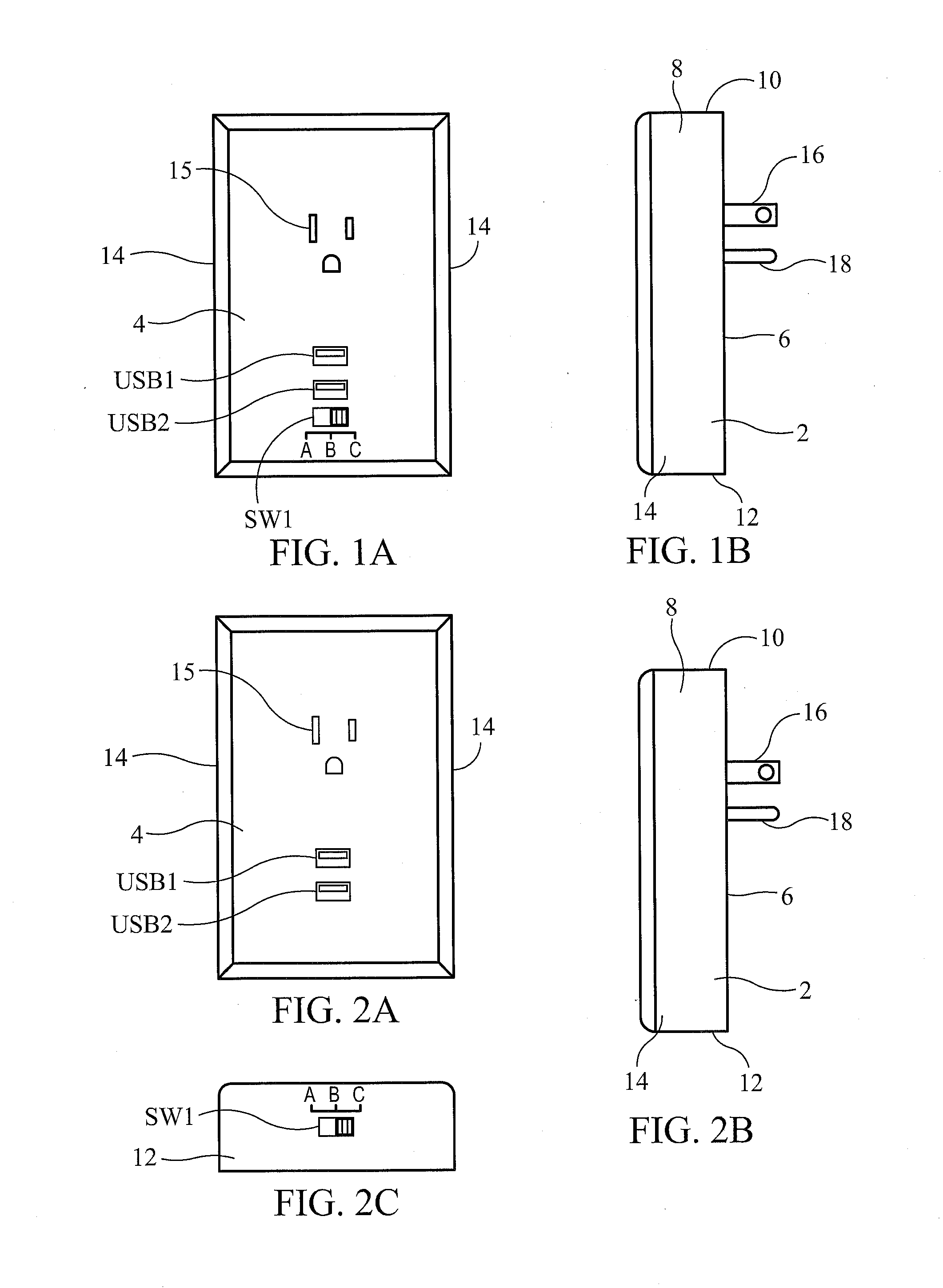
[0023]Referring initially to FIGS. 1 and 2 of the drawings, it will be seen that a USB wall plate charger constructed in accordance with the present invention includes a housing 2 which is preferably formed with a rectangular shape, but other shapes, such as square, round, oblong or polygonal, may be suitable for forming the housing of the present invention. The housing 2 includes a front wall 4, a rear wall 6 situated opposite the front wall 4, and one or more side walls 8 interposed between the front wall 4 and the rear wall 6 of the housing. For the rectangularly-shaped housing 2 shown in FIGS. 1 and 2, the housing includes a top wall 10, a bottom wall 12 situated opposite the top wall 10 and two lateral side walls 14, defining the side walls 8 of the housing of the wall plate charger having a rectangular (or square) shape. A 120 volt AC power outlet 15 is preferably provided on the front wall 4 of the housing 2.

[0024]A pair of male electrical prongs 16 and a male ground prong 18...


PUM


Abstract

A USB wall plate charger for charging an external electronic device is mountable to a common 120 volt AC wall outlet, and includes a power supply to convert the 120 volts AC to +5 volts DC, and a charging profile configuration circuit. A charging profile selection switch is provided for the user to select a desired charging profile that is compatible with the electronic device to be charged.

Description

CROSS-REFERENCE TO RELATED APPLICATIONS[0001]This application is related to U.S. Provisional Application Ser. No. 61 / 584,561, filed on Jan. 9, 2012, and entitled “USB Wall Plate Charger”, the disclosure of which is incorporated herein by reference and on which priority is hereby claimed.BACKGROUND OF THE INVENTION[0002]1. Field of the Invention[0003]The present invention relates to USB chargers and charging circuits for charging the batteries of electronic devices.[0004]2. Description of the Prior Art[0005]Nowadays, there are many brands and designs of smartphones, cellular phones, internet tablets and portable electronic devices, including Apple's iPod / iPhone / iPad™ devices, the Android™ cellular phone or tablet, and others, that use the DC power source from their internal batteries. The batteries of these devices need to be recharged through a USB port. Although the wiring configuration and charge power (charge voltage and current) allowed for normal operating range of a USB port i...

Claims


Application Information

Patent Timeline
Patent Type & Authority Applications(United States)
IPC IPC(8): H02J7/00
CPCH02J7/0004H02J2007/0062H01R25/006H01R24/68H01R31/065H01R13/70H02J7/00036H02J7/00047H02J7/00
Inventor TINAPHONG, PRAPAN PAULTITTLE, WILLIAM ROGERRINEHART, JAMES K.WOODLING, YIQI W.GEISE, S. IANCASKEY, HENRY D.
Owner VOXX INT CORP
Why Eureka
Try Eureka