Device and method for single-handedly self-photographing
- Summary
- Abstract
- Description
- Claims
- Application Information
AI Technical Summary
Benefits of technology
Problems solved by technology
Method used
Image
Examples
first embodiment
(a) First Embodiment
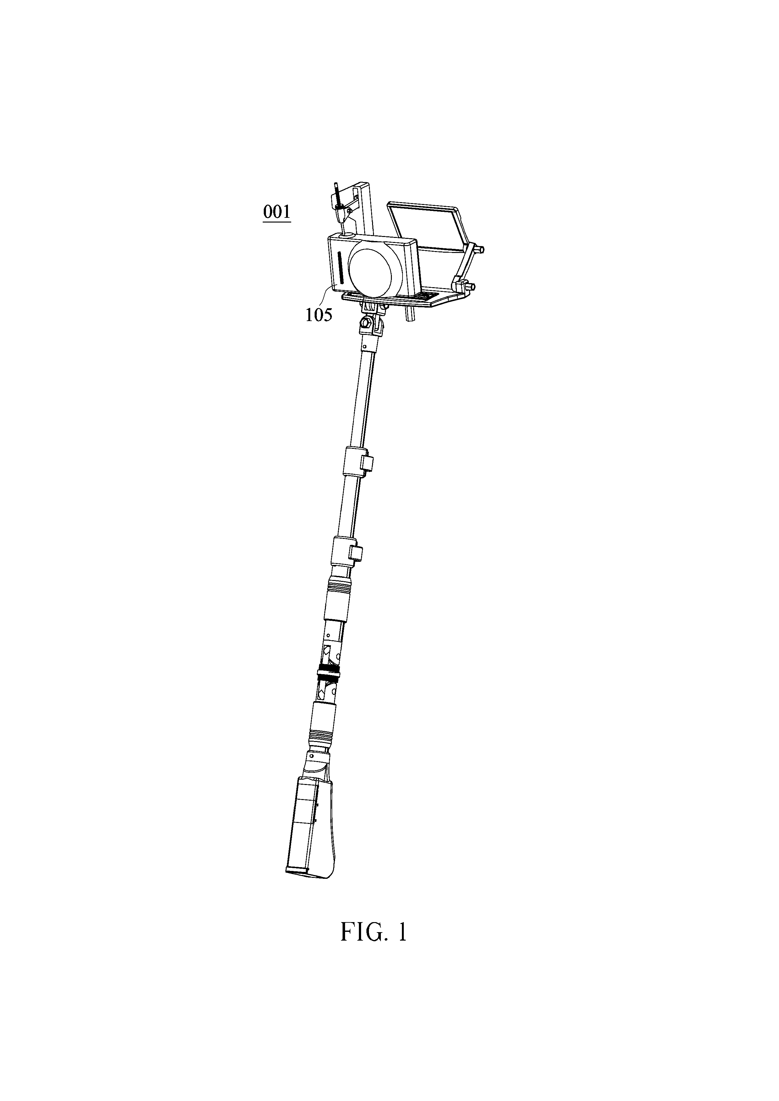
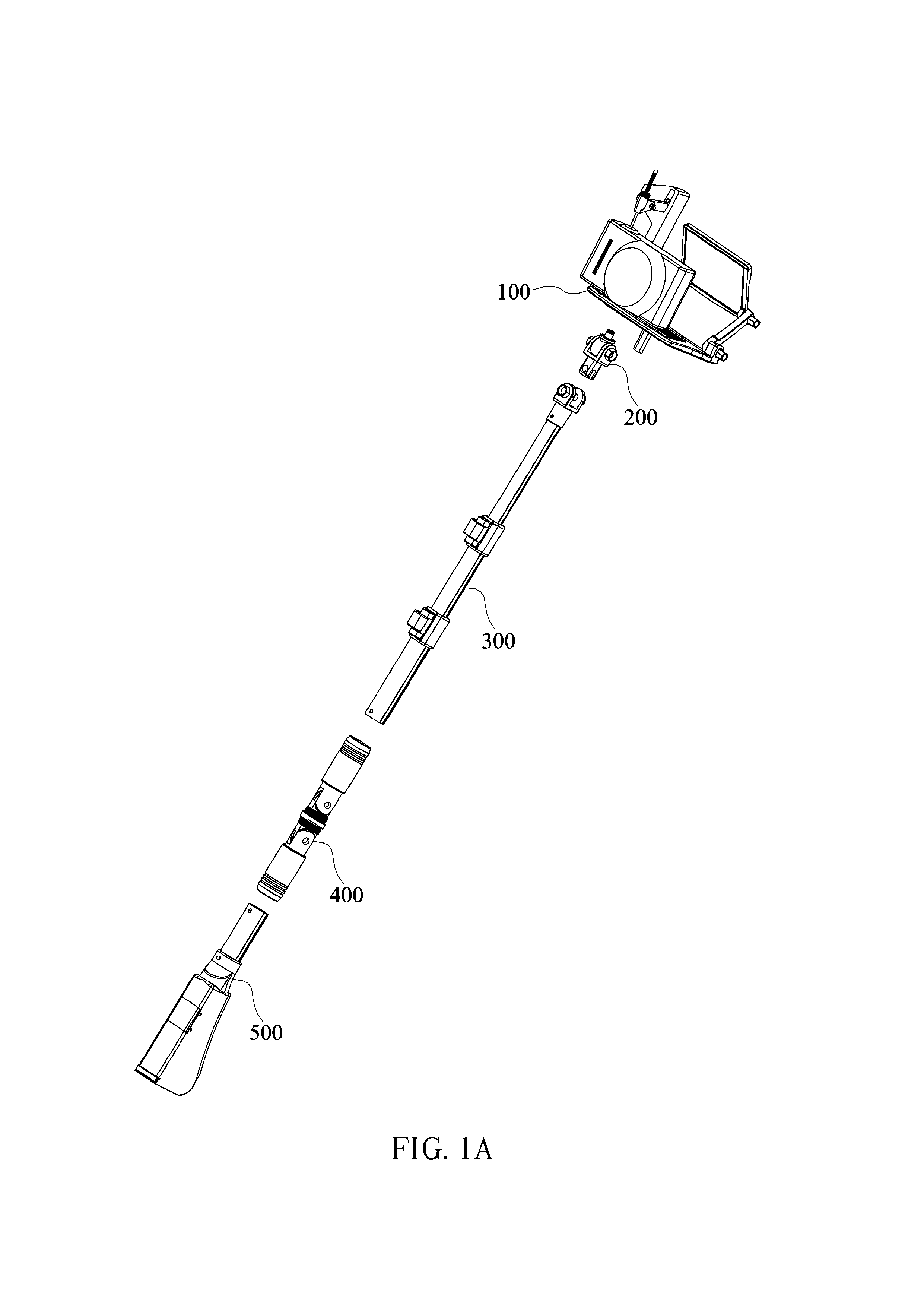
[0046]FIG. 1 is an exemplary illustration of a self-photographing device 001 of the present invention with a digital camera 105 mounted thereon. Referring to FIG. 1A, the self-photographing device 001 comprises a picture-taking unit 100, a stage rotation unit 200, a telescopic pole unit 300, a folding joint unit 400, and a grip unit 500. The operations and functions of the components of the respective units will be described in detailed in the following.
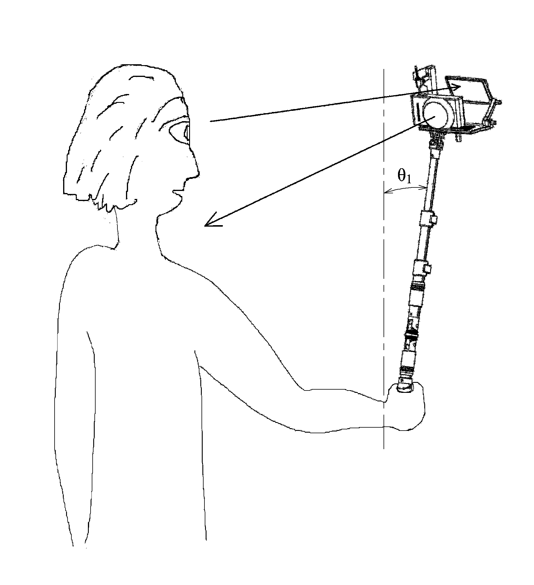
[0047]Referring to FIG. 2, the self picture-taking device 001 is single-handedly held and operated for self photographing. Thus, the photographer can afford a free hand for keeping himself balanced in certain situations. The extendable telescopic pole unit 300 enables the photographer to position the digital camera 105 at a distance of least a meter from himself to successfully contain required targets within picture frame. A mirror 101 provides, when properly adjusted, a reflection of the image shown on the camer...
second embodiment
(b) Second Embodiment
[0057]FIG. 15 shows a schematic drawing illustrating of a manually triggering self-photographing device 600, which is mostly similar to the self-photographing device 001. In other words, the second embodiment shares almost the same components with the first one. The only difference between these two embodiments is that, instead of the aforementioned shutter triggering module 110 and grip unit 500, a lever unit 610 shown in FIG. 16 and a grip unit 620 shown in FIG. 17 are used in this embodiment.
[0058]Referring to FIG. 16A and FIG. 17, the lever unit 610 includes a restoring spring 611, a hinge 612, a pulling rope 613, and a beam 614; and the grip unit 620 comprises a pushing rod 621, a hinge 622, a trigger 623, a trigger handle 624 coupled to the trigger 623 with the hinge 622, and a spring 625. When the trigger 623 is squeezed toward the trigger handle 624, the pulling rope 613 is pulled down by the pushing down rod 621, which results in a downward motion of th...
PUM
 Abstract
Description
Claims
Application Information
 - R&D
- Intellectual Property
- Life Sciences
- Materials
- Tech Scout
- Unparalleled Data Quality
- Higher Quality Content
- 60% Fewer Hallucinations
Browse by: Latest US Patents, China's latest patents, Technical Efficacy Thesaurus, Application Domain, Technology Topic, Popular Technical Reports.
© 2025 PatSnap. All rights reserved.Legal|Privacy policy|Modern Slavery Act Transparency Statement|Sitemap|About US| Contact US: help@patsnap.com


