
Hinge assembly having linear movement and slide type electronic device

Active Publication Date: 2013-07-11
WISTRON CORP
View PDF13 Cites 11 Cited by
  • Summary
  • Abstract
  • Description
  • Claims
  • Application Information

AI Technical Summary

Benefits of technology

The patent proposes a hinge assembly with linear and rotational movement for a slide-type electronic device. The assembly is simple in structure, allowing for easy assembly without pre-installation of components. This simplifies the assembly process for slide-type electronic devices.

Problems solved by technology

To achieve linear and rotational movements, such a hinge assembly has complicate structure.
Since some components have to be pre-installed into the cover-body or the main-body, the assembling process for the slide-type electronic device is complicated and the internal structures of the cover-body and the second body are also complicated.
In the art, the assembling process for the slide-type electronic device is complicate.

Method used


Image

  • Hinge assembly having linear movement and slide type electronic device
  • Hinge assembly having linear movement and slide type electronic device
  • Hinge assembly having linear movement and slide type electronic device

Examples


first embodiment

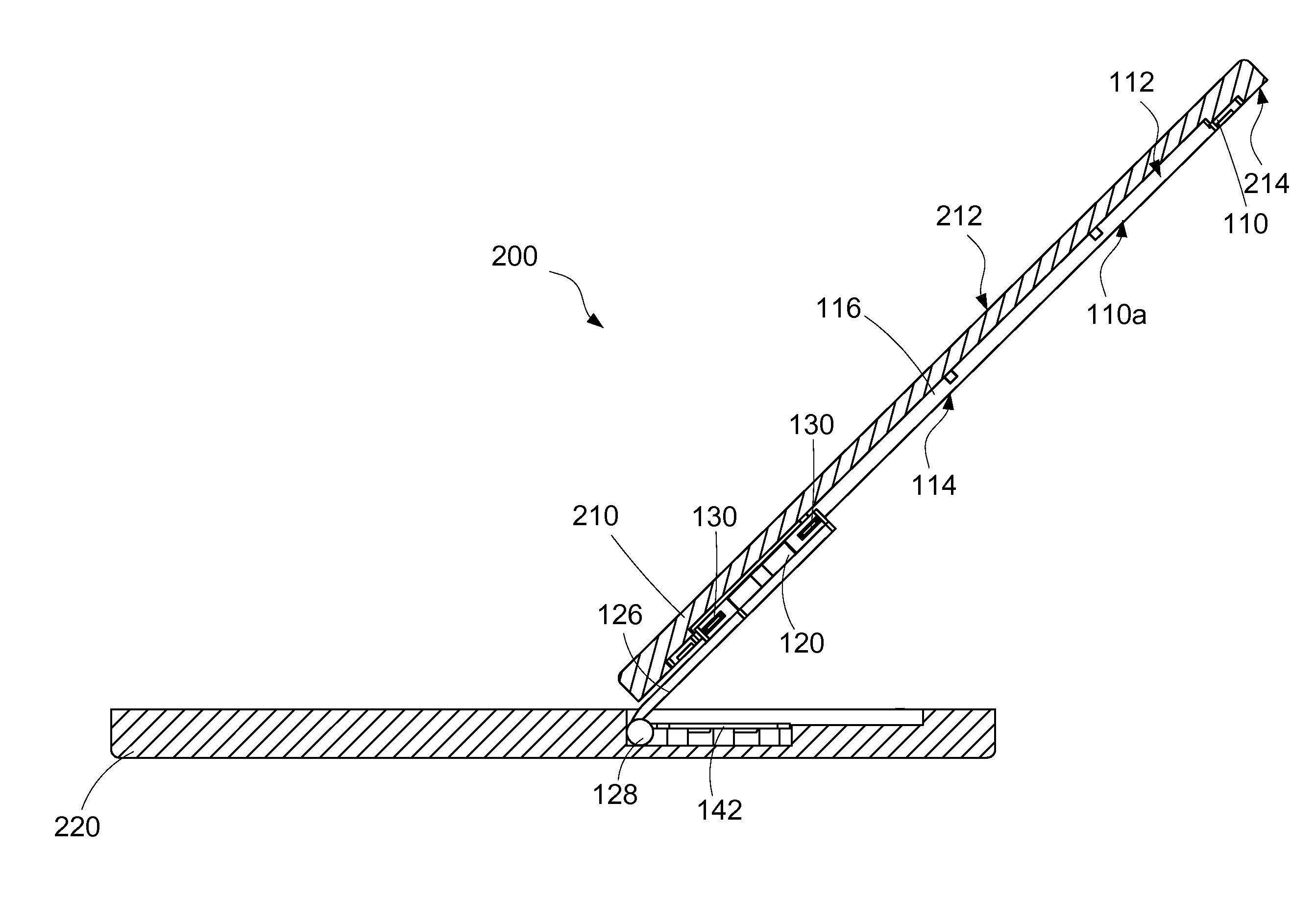
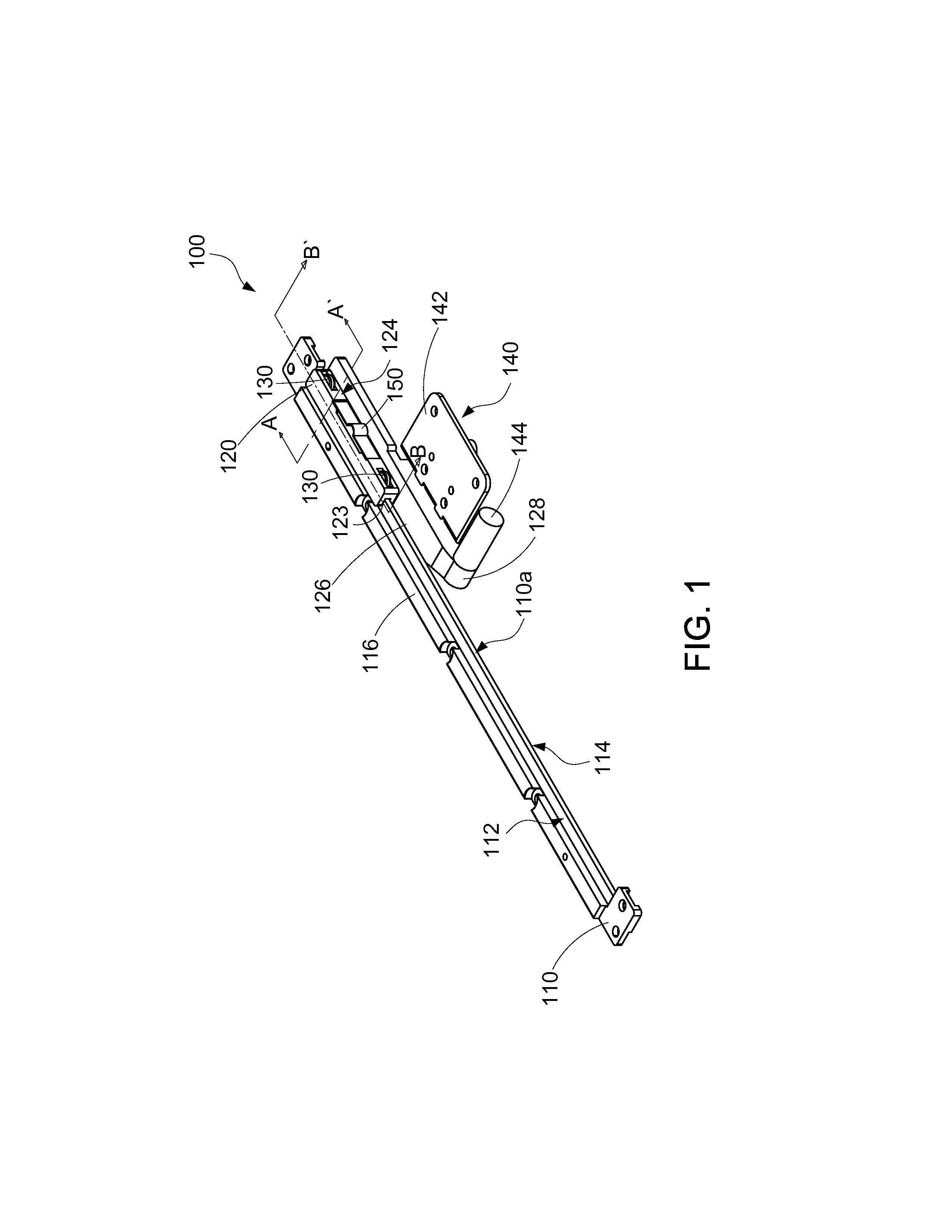
[0038]Please refer to FIG. 9 and FIG. 10, in which a slide-type electronic device 200 is shown. The slide-type electronic device 200 includes a first body 210, a second body 220, and at least one pairs of hinge assemblies 100. The first body 210 and the second body 220 hereinafter are the aforementioned first article and second article. The amount of the hinge assemblies 100 is not restricted, and a pair of hinge assemblies 100 is taken as illustrations in this embodiment.

[0039]As shown in FIG. 9 and FIG. 10, the first body 210 includes a front surface 212 and a back surface 214. The second body 220 includes a top surface 222.

[0040]As shown in FIG. 9 and FIG. 10, a display screen 216 is disposed on the front surface 121. In at least one example, the display screen 216 is disposed on the second body 220. each of the hinge assemblies 100 is provided for combining the first body 210 with the second body 220, such that the first body 210 is capable to move linearly and rotate on the se...

second embodiment

[0050]Please refer to FIG. 16, in which a slidable element 120 is shown. The slidable element 120 further includes at least two auxiliary rolling members 160, disposed on the slidable element 120 in a rotatable manner. And the slidable element 120 in this embodiment is modified according to the auxiliary rolling members 160.

[0051]The slidable element 120 of the second embodiment further includes two depressions 125, for receiving the two main rolling members 130. And at least part of each main rolling member 130 protrudes on the guiding surface 124 for contacting with the inner wall of the elongated slot 21; or at least part of each main rolling member 130 protrudes on the sliding surface 122 for contacting with the guiding rail 110. In the second embodiment, each main rolling member 130 protrudes on the sliding surface to contact with the other part of the guiding rail 110 and is not located in the chute 123. Two roller seats 180 are respectively disposed to two ends of the slidab...


PUM


Abstract

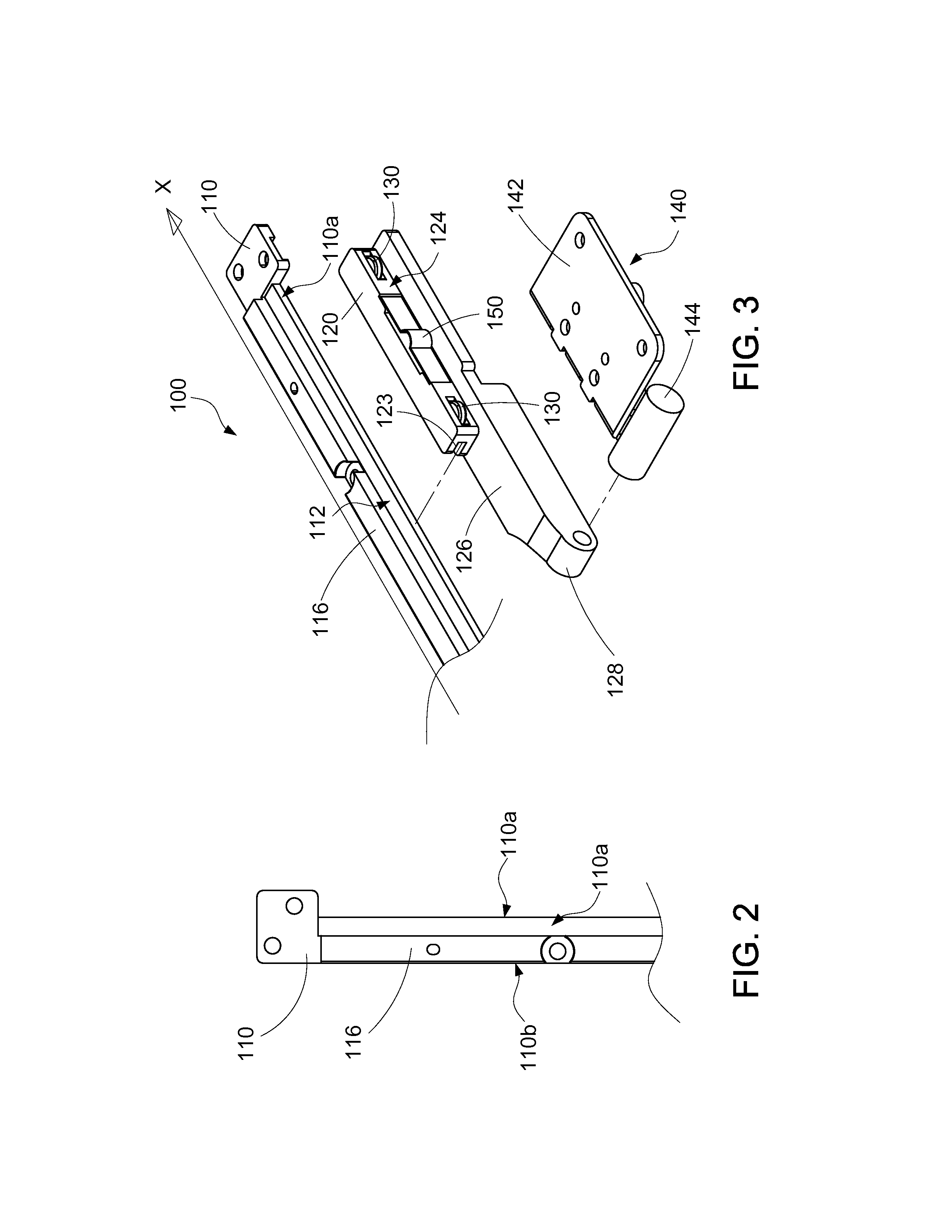
A hinge assembly includes a guiding rail, at least one protruding block, a slidable element, and a rotatable element. The guiding rail includes a first side and a second side surface opposite to each other. The guiding rail further includes a first edge and a second edge in parallel to a longitudinal direction of the guiding rail. The protruding block is disposed on the first side surface. The width of the protruding block is smaller than that of the first side surface, and a gap exists between the protruding block and the first edge. The slidable element includes a sliding surface and a guiding surface opposite to each other. The first edge of the guiding rail inserts into a chute formed on the sliding surface to move the slidable element along the first edge. The rotatable element is pivoted to the slidable element to rotate on the slidable element.

Description

CROSS-REFERENCES TO RELATED APPLICATIONS[0001]This non-provisional application claims priority under 35 U.S.C. §119(a) on Patent Application No. 101100826 filed in Taiwan, R.O.C. on 2012 / 01 / 09, the entire contents of which are hereby incorporated by reference.BACKGROUND[0002]1. Technical Field[0003]This disclosure us relates to a hinge assembly, and more particular to a hinge assembly having linear and rotational movements and a slide-type electronic device having the hinge assembly.[0004]2. Related Art[0005]A slide-type electronic device in the art includes a cover-body and a main-body. The cover-body is combined with the main-body in a slidable manner. Usually, the cover-body can only moves linearly on the main-body. In the art, a fold-type electronic device also includes a cover-body and a main-body. The cover-body is pivoted to the main-body, such that the cover-body can rotate on the main-body to form an included angle between the cover-body and the main-body. A slide-type elec...

Claims


Application Information

Patent Timeline
IPC IPC(8): H05K5/02E05D11/04E05D7/00
CPCG06F1/1616G06F1/1624Y10T16/5453Y10T16/5377G06F1/1681
Inventor LIAO, CHIEN-JUNGLEE, YAO-TINGLEE, MING-HSI
Owner WISTRON CORP
Learn More