Scanning apparatus

US20070223066A1Active Publication Date: 2007-09-27LITE ON TECH CORP

Image

  • Scanning apparatus
  • Scanning apparatus
  • Scanning apparatus

Examples


Embodiment Construction

[0019]To further understand the objects, constructions, features, and functions of the invention, the detailed description is now given below through the embodiments.

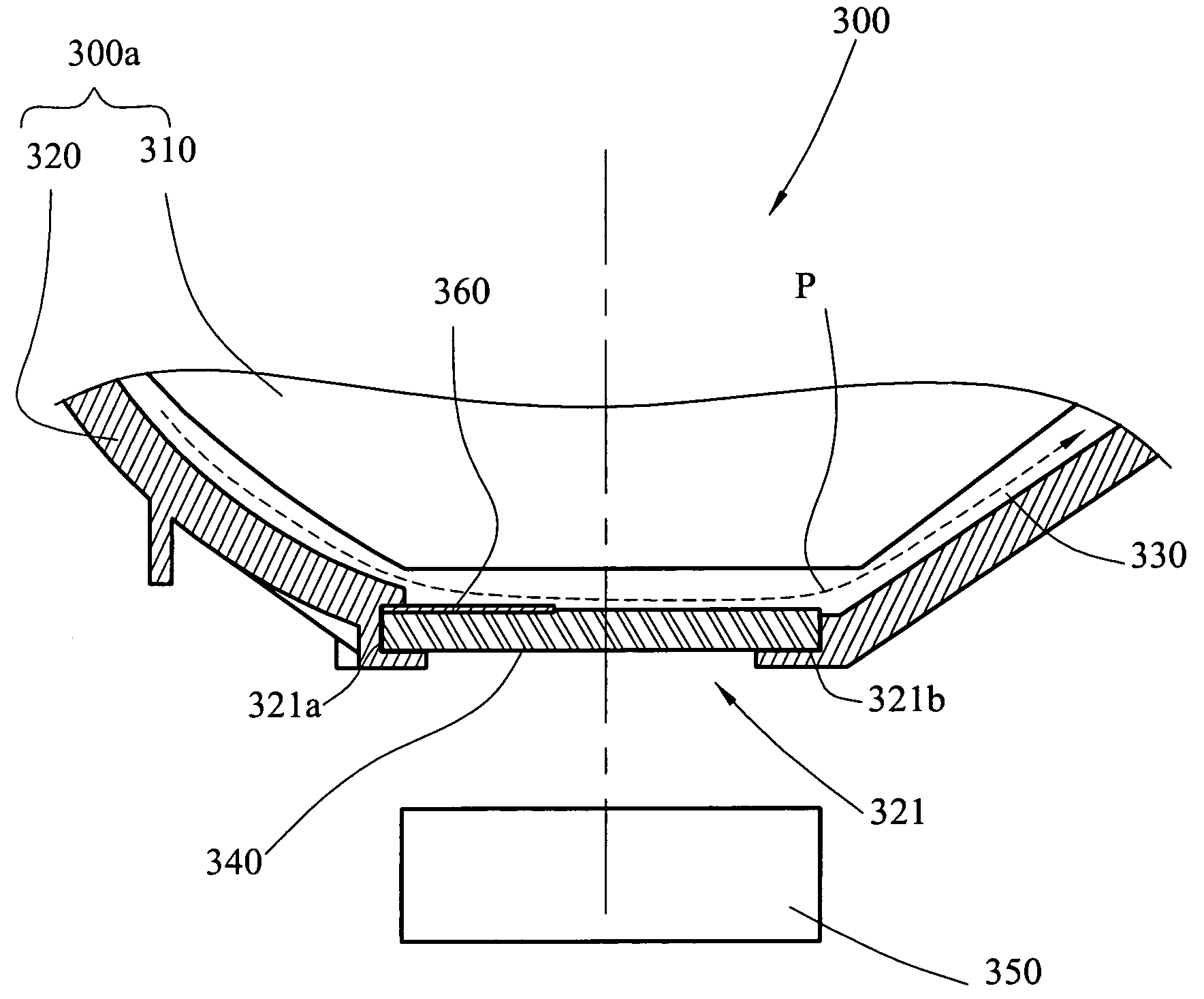
[0020]Referring to FIGS. 3 and 4, a scanning apparatus 300 of an embodiment of the invention is provided, which is either an independent sheetfed scanner or a part of a multi-functional-printer (MFP). The scanning apparatus 300 includes a body 300a, a transparent plate 340, a scanning module 350, and a color reference slice 360.

[0021]The body 300a includes a cover 310 and a base 320. The bottom surface of the cover 310 is convex-shaped and the top surface of the base 320 is concave-shaped, such that the cover 310 and the base 320 are matched with each other. The cover 310 is disposed above the base 320 and a spacing distance exists there-between to form a paper-feeding track 330 within the body 300a for a paper sheet P to move there-through. Moreover, a scanning window 321 is formed on the base 320, corresponding to a s...


PUM


Abstract

A scanning apparatus includes a body, a transparent plate, a scanning module, and a color reference slice. A paper-feeding track is formed within the body, and a scanning window is formed at a side wall of the paper-feeding track. A coupling groove is formed at an edge of the scanning window. Both the transparent plate and the color reference slice have an edge being inserted into the coupling groove, such that the transparent plate covers the scanning window while the color reference slice leans against a side surface of the transparent plate facing the paper-feeding track. The scanning module is disposed within the body corresponding to the scanning window, such that a paper to be scanned and the color reference slice are located in the same plane, and the color reference slice and the paper are scanned under the same optical conditions.

Description

CROSS-REFERENCE TO RELATED APPLICATIONS[0001]This non-provisional application claims priority under 35 U.S.C. § 119(a) on Patent Application No(s). 095204992 filed in Taiwan, R.O.C. on Mar. 24, 2006 the entire contents of which are hereby incorporated by reference.BACKGROUND OF THE INVENTION[0002]1. Field of Utility model[0003]The present invention relates to a sheetfed scanning apparatus, and more particularly to a structure for mounting a transparent plate and a color reference slice in the sheetfed scanning apparatus.[0004]2. Related Art[0005]The scanning apparatus in a sheetfed scanner or multi-functional-printer (MFP) has a transparent plate made of transparent materials such as glass, and paper sheets moving on the transparent plate are scanned by a scanning module, so as to produce and then output the image data. The transparent plate is mainly used for separating the paper sheets from the scanning module, so as to prevent the paper sheets from contacting the scanning module ...

Claims


Application Information

Patent Timeline
27 Sep 2007
Publication
US20070223066A1
IPC
H04N1/04
CPC
H04N1/00519; H04N1/00559; H04N1/125; H04N1/1235; H04N1/1245; H04N1/12
Inventors
LIU, CHUN-LIANG; LIU, JEN-CHIEH