Motor having a stator and a rotor made of soft magnetic powder material

Inactive Publication Date: 2007-05-24
DONGSEO ELECTRONICS
View PDF6 Cites 5 Cited by
  • Summary
  • Abstract
  • Description
  • Claims
  • Application Information

AI Technical Summary

Benefits of technology

[0015] Accordingly, the present invention has been made keeping in mind the above problems occurring in the prior art, and an object of the present invention is to provide a stator for a motor which is made of soft magnetic powder material so that, when a motor assembly process is c

Problems solved by technology

However, in the conventional motor 10, because the stator 12 is made of layered silicon steel plates, when the stator 12 is force-fitted into the shell 11, a portion of the stator 12 at which stress is concentrated may be physically damaged by torsion, for example, the layered silicon steel plates may be separated from each other or may be bent.
Consequently, this makes insertion of the stator 12 into the shell 11 difficult.
In addition, this makes insertion of the rotating shaft 14 into the rotor 13 difficult.
However, in the case where the motor 10

Method used


Image

  • Motor having a stator and a rotor made of soft magnetic powder material
  • Motor having a stator and a rotor made of soft magnetic powder material
  • Motor having a stator and a rotor made of soft magnetic powder material

Examples


Example

FIRST EMBODIMENT

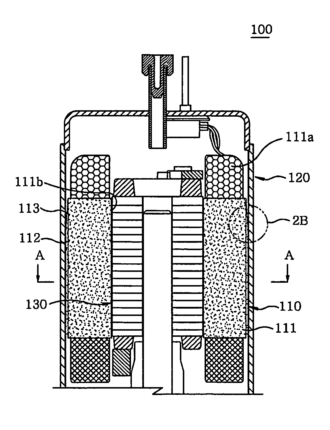
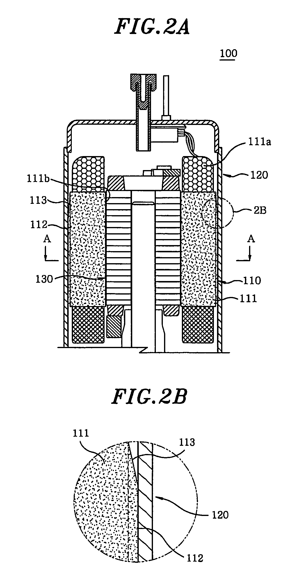
[0026]FIGS. 2A and 2B are sectional views of a motor 100 having a stator 110 made of soft magnetic powder material, according to the present invention. As shown in the drawing, the stator 110 made of soft magnetic powder material according to the present invention includes a stator body 111 and a plurality of compression beads 112, which are formed on the outer surface of the stator body 111. The stator 110 is formed by compressing soft magnetic powder.

[0027] The stator body 111 is fastened to the inner surface of a shell 120 of the motor 100. A coil 111a is wound around the stator body 111, and a through hole 111b is longitudinally formed through the stator body 111 so that a rotor 130 fitted over a rotating shaft 131 is rotatably installed in the through hole 111b. Furthermore, the stator body 111 has a cross-section, which has a circular or polygonal shape or the shape of a figure comprising a curved line and a straight line. Several compression beads 112 are fo...

Example

SECOND EMBODIMENT

[0041]FIGS. 4A to 4C are sectional views of a motor 200 having a rotor 210 made of soft magnetic powder material, according to the present invention. As shown in the drawing, the rotor 210 made of soft magnetic powder material includes a rotor body 211, and a plurality of compression beads 212, which are provided on the inner surface of the rotor body 211. The rotor 210 is formed by compressing soft magnetic powder.

[0042] The rotor body 211 is rotatably provided in a stator 220 installed in a shell 240 of the motor 200. The rotor body 211 is cylindrical and has in a central portion thereof a fastening part 211a, into which a rotating shaft 230 is force-fitted.

[0043] In the case of the conventional art, in which a rotor body is manufactured by layering a plurality of silicon steel plates, a fastening part must be formed into a simple hole shape. However, in the present invention, because the rotor body 211 is made of compressed soft magnetic powder, it is not limi...


PUM


Abstract

A stator includes a stator body and a plurality of compression beads formed on an outer surface of the stator body to reduce a contact surface between the stator body and an inner surface of the shell, the plurality of compression beads being compressed by the inner surface of the shell and thus held therein when the stator is fitted into the shell. Further, the plurality of compression beads is oriented in a direction in which the stator body is fitted into the shell, and each of the plurality of compression beads has an inclined guide part on an end corresponding to an end of the stator body that is first fitted into the shell, to guide the fitting of the stator body.

Description

FIELD OF THE INVENTION [0001] The present invention relates generally to a motor having a stator and a rotor made of soft magnetic powder, and, more particularly, to a motor having a stator and rotor, which are made of soft magnetic powder so that the stator and the rotor can be smoothly and force-fitted into a shell of the motor without being physically damaged during a motor assembly process. BACKGROUND OF THE INVENTION [0002] As well known to those skilled in the art, motors are devices which convert electric energy into mechanical energy to provide rotating force. The motors are widely used in industrial apparatuses as well as in domestic electronic products. As examples of domestic electronic products in which the motors are used, there are washing machines, cleaners, optical disk players, hard disk-drives of computers, and compressors, which are provided in air cooling devices, such as air-conditioners and refrigerators, to condense refrigerants into liquid states. [0003] A co...

Claims


Application Information

Patent Timeline
IPC IPC(8): H02K15/12H02K1/00H02K1/06
CPCH02K1/02H02K1/185H02K1/28
Inventor KU, JIN-KWAN
Owner DONGSEO ELECTRONICS
Why Eureka
Try Eureka