Device for electrostimulation

a technology of electrostimulation and eye, which is applied in the direction of optics, artificial respiration, instruments, etc., can solve the problems of retinal degeneration, eye electric stimulation, and significant device demands

Active Publication Date: 2013-07-18
OKUVISION
View PDF2 Cites 21 Cited by
  • Summary
  • Abstract
  • Description
  • Claims
  • Application Information

AI Technical Summary

Benefits of technology

[0036]In view of the above, it is one object of the present invention to improve the device mentioned at the outset such that it establishes a good, reproducible contact between the stimulation electrode and the eye to be treated but, at the same time, can also be used at home without problems by a blind or almost blind patient.

Problems solved by technology

Retinal degeneration is a significant cause of blindness in industrialized countries.
This results in significant demands on the device mentioned at the outset.
A disadvantage of all devices described insofar is that the electric stimulation of the eye is brought about by electrodes placed onto the skin, as also already known from other fields of application of electrostimulation.
However, due to the difficulties associated therewith, iontophoresis has not found widespread use.
However, these effects are unacceptable for the therapeutic application planned within the scope of the present application.
This is because if the skin resistance is very different from application to application, it proves impossible to ensure that the electric field strength generated on the retina is reproducible and that therapeutic success can be expected.
These contact lenses are considered to be difficult to tolerate and painful because the curvature thereof is not precisely fitted to the eye for reasons of costs.
These electrodes, which are also known as Hawlina electrodes, are significantly more tolerable than the metallically coated contact lenses, but are difficult to handle for blind patients because they cannot monitor the precise shape and the seat of the wire loop.
Adhesive plasters are generally used for fixation to the head, which is disadvantageous in that the position of the electrode can change over the whole duration of the stimulation.
These electrodes have been tested many times in ERG, they are the most tolerable of all the known ERG electrodes, but are disadvantageous in that the medical practitioner or orderly requires great manual dexterity for the application thereof in clinical practice.
Hence these electrodes cannot be applied independently by patients.

Method used


Image

  • Device for electrostimulation
  • Device for electrostimulation
  • Device for electrostimulation

Examples


Embodiment Construction

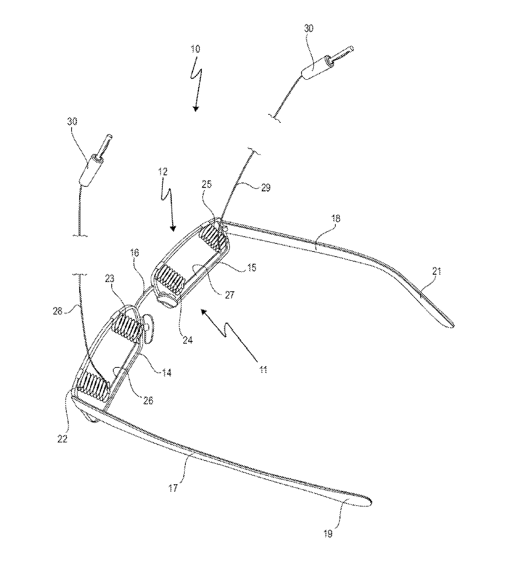
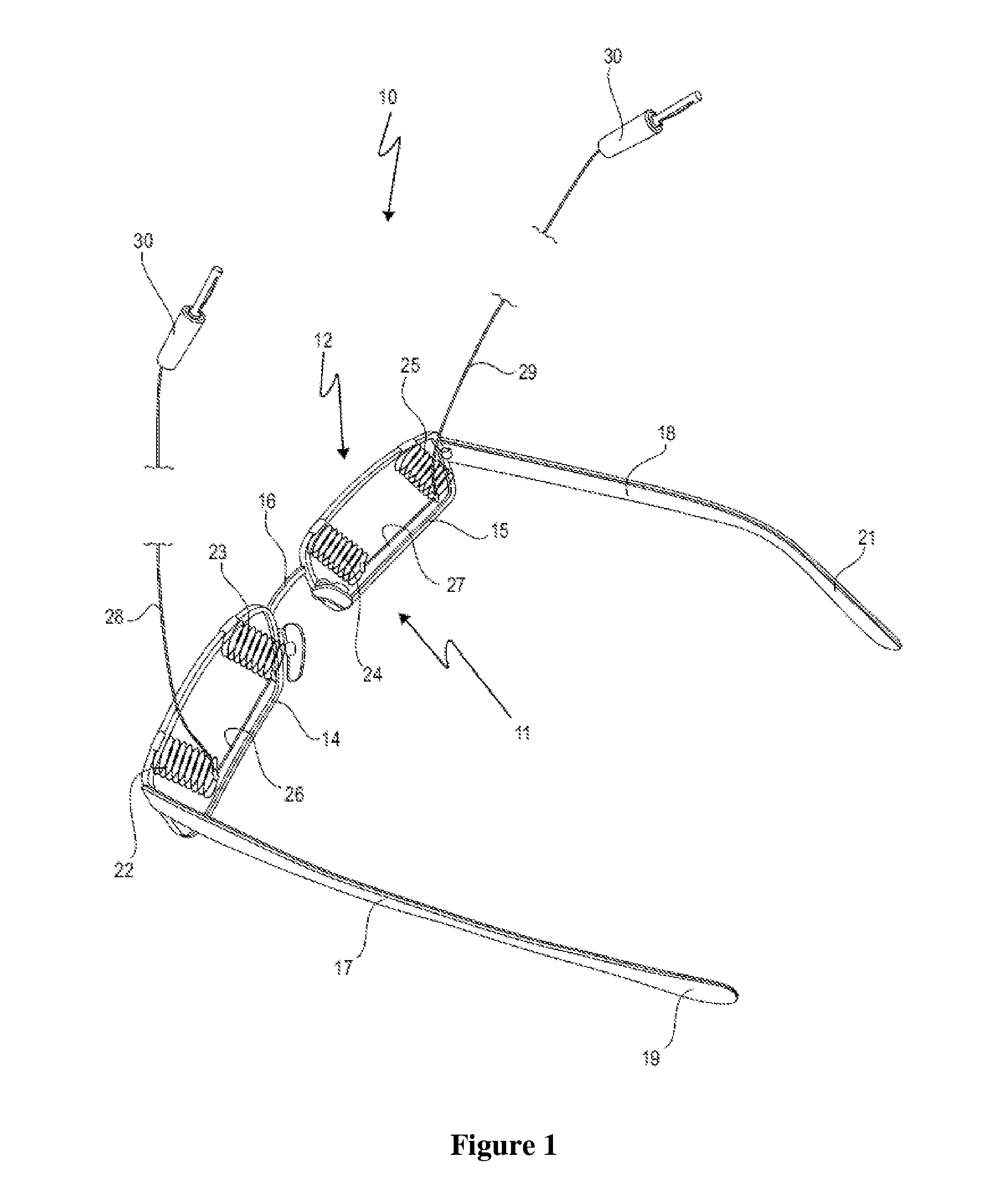
[0104]In FIG. 1, a device denoted by 10 is shown, which serves for electrostimulation of the eye. The device 10 comprises a spectacles-like supporting frame 11, which has a nose part 12, on which two frames 14 and 15 are formed which correspond to the position of the eye of the patient. The two frames 14 and 15 are interconnected by a nose bracket 16.

[0105]As conventional with spectacles, the nose part 12 is provided with an arrangement for keeping the supporting frame 11 on the head of a patient. This arrangement has two lateral arms 17 and 18, which are hinged on the nose part 12 in a foldable fashion and have a bent embodiment at their respective free end 19 and 21 such that the supporting frame 11 can be fitted to the physiognomy of a patient in an optimum fashion.

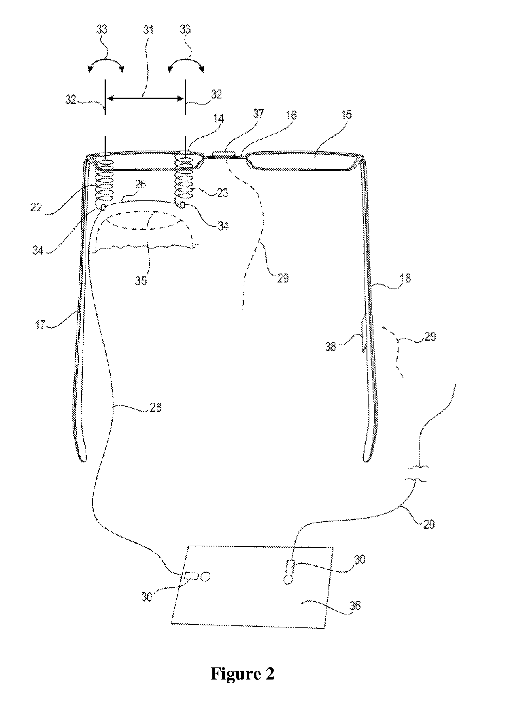
[0106]Two elastically resilient electrode holders 22 and 23, and also 24 and 25, are provided on each frame 14 and 15, said electrode holders being sprung in the direction of the lateral arms 17 and 18 and also perpend...


PUM


Abstract

A device for electrostimulation of the eye is provided with a spectacles-like supporting frame (11) which has a nose part (12) and an arrangement (17, 18), connected to the nose part (12), for holding the supporting frame (11) on the head of the patient, wherein at least one stimulation electrode (26, 27) is arranged on the nose part (12). Furthermore, provision is made for at least two electrode holders (22, 23, 24, 25) on the nose part (12), between which electrode holders an interchangeable, wire-shaped stimulation electrode (26, 27) is clamped (FIG. 1).

Description

CROSS-REFERENCE TO RELATED APPLICATIONS[0001]This is a continuation application of co-pending international patent application PCT / EP2011 / 050447, filed Jan. 14, 2011 and designating the United States, which was published in German as WO 2011 / 086150 A2, and claims priority to German patent application DE 10 2010 027 201.9, filed Jul. 8, 2010, and German utility model DE 20 2010 001 150.7, filed Jan. 15, 2010. The entire contents of these prior applications are incorporated herein by this reference.BACKGROUND OF THE INVENTION[0002]1. Field of the Invention[0003]The present invention relates to a device for electrostimulation of the eye, comprising a spectacles-like supporting frame which has a nose part and an arrangement, connected to the nose part, for holding the supporting frame on the head of the patient, wherein at least one stimulation electrode is arranged on the nose part.[0004]2. Related Prior Art[0005]Such a device has been disclosed in US 2004 / 0176820 A1.[0006]The known de...

Claims


Application Information

Patent Timeline
Patent Type & Authority Applications(United States)
IPC IPC(8): A61N1/36
CPCA61N1/04G02C2200/26G02C11/00A61N1/36046
Inventor EIPPER, CARMENWROBEL, WALTER G.
Owner OKUVISION
Why Eureka
Try Eureka