Linear pipe recovery/lay tensioners and methods of using same

a technology of linear pipe and tensioner, which is applied in the direction of pipe laying and repair, filament handling, thin material processing, etc., can solve the problems of unbalanced tension command, and achieve the effect of facilitating linear movement of pipe segments and facilitating the placement of drive assemblies

Active Publication Date: 2013-07-25
CONTROL FLOW
View PDF7 Cites 2 Cited by
  • Summary
  • Abstract
  • Description
  • Claims
  • Application Information

AI Technical Summary

Benefits of technology

[0011]In still other embodiments of the linear pipe tensioners, the upper and lower frames are not required to be pivotally connected and the one or more cylinders are not required to be present, although one or more of these features can be included. In these embodiments, one or more gripping pads is operatively associated with either the upper or lower tracks. One or more of these gripping pads comprise a compliant member having a slot and a gripping member disposed within the first slot such that compression of the compliant member causes at least a portion of the gripping member to be exposed from the slot. In so doing, the gripping member engages a pipe segment to facilitate linear movement

Problems solved by technology

The tension command will become unbalanced and the control system will drive the pu

Method used


Image

  • Linear pipe recovery/lay tensioners and methods of using same
  • Linear pipe recovery/lay tensioners and methods of using same
  • Linear pipe recovery/lay tensioners and methods of using same

Examples


Embodiment Construction

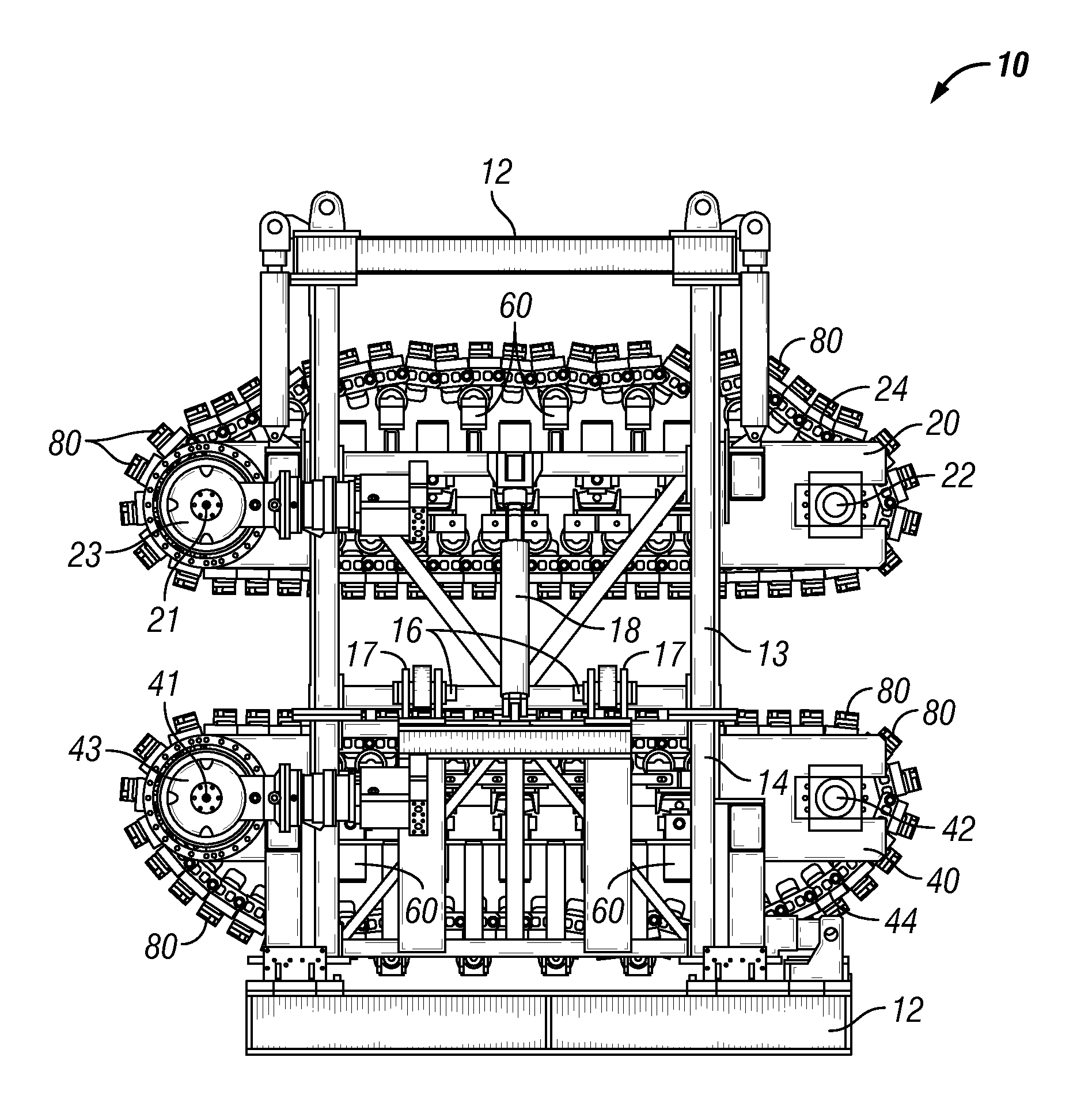
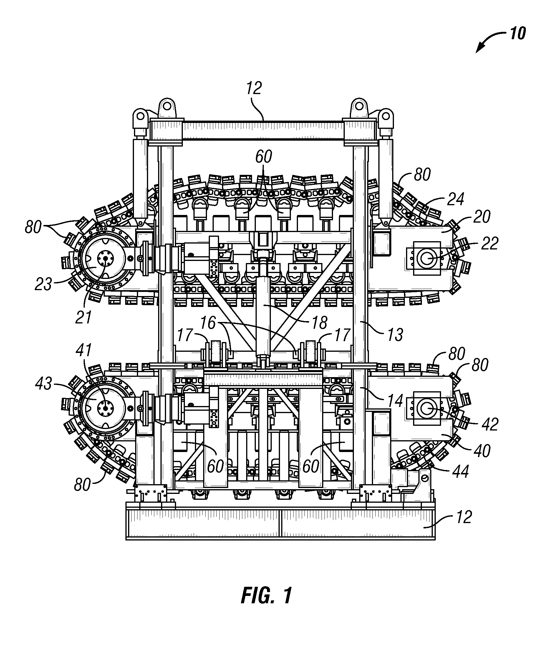
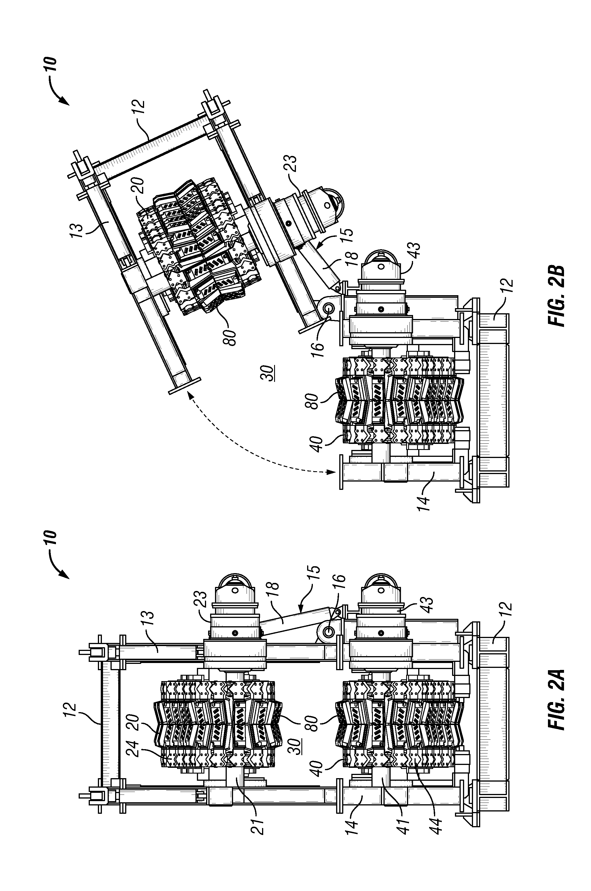
[0027]Referring now to FIGS. 1-10, in one specific embodiment linear pipe tensioner 10 includes frame 12. In this particular embodiment, frame 12 comprises upper frame member 13 and lower frame member 14 rotatably connected to each other by pivot assembly 15. As shown in FIGS. 1, 2A, and 2B, pivot assembly 15 comprises two hinge members comprising pins 16 inserted through brackets 17, and cylinder 18. Pivot assembly 15 permits the movement of upper track assembly 20 along the trajectory of the arrow shown in FIG. 2B to facilitate insertion of a pipe segment (not shown) within space 30 between upper track assembly 20 and lower track assembly 40.

[0028]Although frame 12 is shown as having upper and lower frame members 13, 14 pivotally connected by pivot assembly 15, it is to be understood that frame 12 is not required to have these components. To the contrary, frame 12 may be a structure that is not capable of being opened to facilitate insertion of a pipe segment.

[0029]Upper track ass...


PUM


Abstract

Linear pipe recovery/lay tensioners can include one or more pivot assemblies for rotatably moving an upper track away from a lower track to facilitate placement of a pipe segment between the two tracks. In addition, or alternatively, the tensioners can include one or more hydraulic cylinders that provide flexible suspension to the upper and lower tracks so the tracks can move and rotate as necessary due to differing pipe segment shapes. In addition, or alternatively, the upper and lower tracks include one or more gripping pad having one or more gripping member that is sheathed by a compliant member until such time as the pipe segment compresses the compliant member causing the gripping member(s) to protrude from the compliant member and bite into the pipe segment. Rotation of the tracks is controlled by a hydraulic pump capable of rotating the tracks at the same rate or at different rates.

Description

BACKGROUND[0001]1. Field of Invention[0002]The invention is directed to roller assemblies for linearly transporting one or more pipe segments, or joints, such as pipelines, and in particular, to linear pipe recovery / lay tensioners for pulling a portion of pipeline from the ocean to be recovered on an offshore lay-barge and for laying pipeline from an offshore lay-barge and onto the ocean floor.[0003]2. Description of Art[0004]Linear pipe tensioners are generally known in the art. These devices are generally installed on a ship or lay barge to facilitate laying or retrieving pipe, such as pipelines and other pipe segments. Linear pipe tensioners are designed to maintain a constant tension on the pipe while the pipes are being lowered into, or retrieved from, the sea during offshore pipe laying operations.[0005]Broadly, linear pipe tensioners consist of an upper and a lower track, each supported in a frame assembly. Pneumatically actuated squeeze bags within the track loops apply sque...

Claims


Application Information

Patent Timeline
IPC IPC(8): F16L1/23
CPCF16L1/23B65H51/14
Inventor ALLOWAY, PATRICK K.PRESTON, KEVIN L.SKILES, LOREN D.
Owner CONTROL FLOW
Why Eureka
Try Eureka