Synchronous hinge head and assembly method

A technology of hinged joints and outer parts, which is applied in the field of synchronous hinged joints and assembly, can solve the problems of small ball contact angle, weakened cage, high manufacturing cost, etc., and achieve the effect of weight reduction, small turning diameter and low manufacturing cost

Inactive Publication Date: 2010-01-27
VOLKSWAGEN AG
View PDF9 Cites 0 Cited by
  • Summary
  • Abstract
  • Description
  • Claims
  • Application Information

AI Technical Summary

Problems solved by technology

[0007] However, the recesses required in US 4,231,232A lead to high manufacturing costs, weaken the cage, and limit the maximum deflection angle of the joint (Beugewinkel), because the ball guide surface of the cage is radially Shrinking
In addition, this type of cage has thicker walls, so that the contact angle of the balls in the raceways of the inner and outer parts becomes correspondingly smaller

Method used


Image

  • Synchronous hinge head and assembly method
  • Synchronous hinge head and assembly method
  • Synchronous hinge head and assembly method

Examples


Embodiment Construction

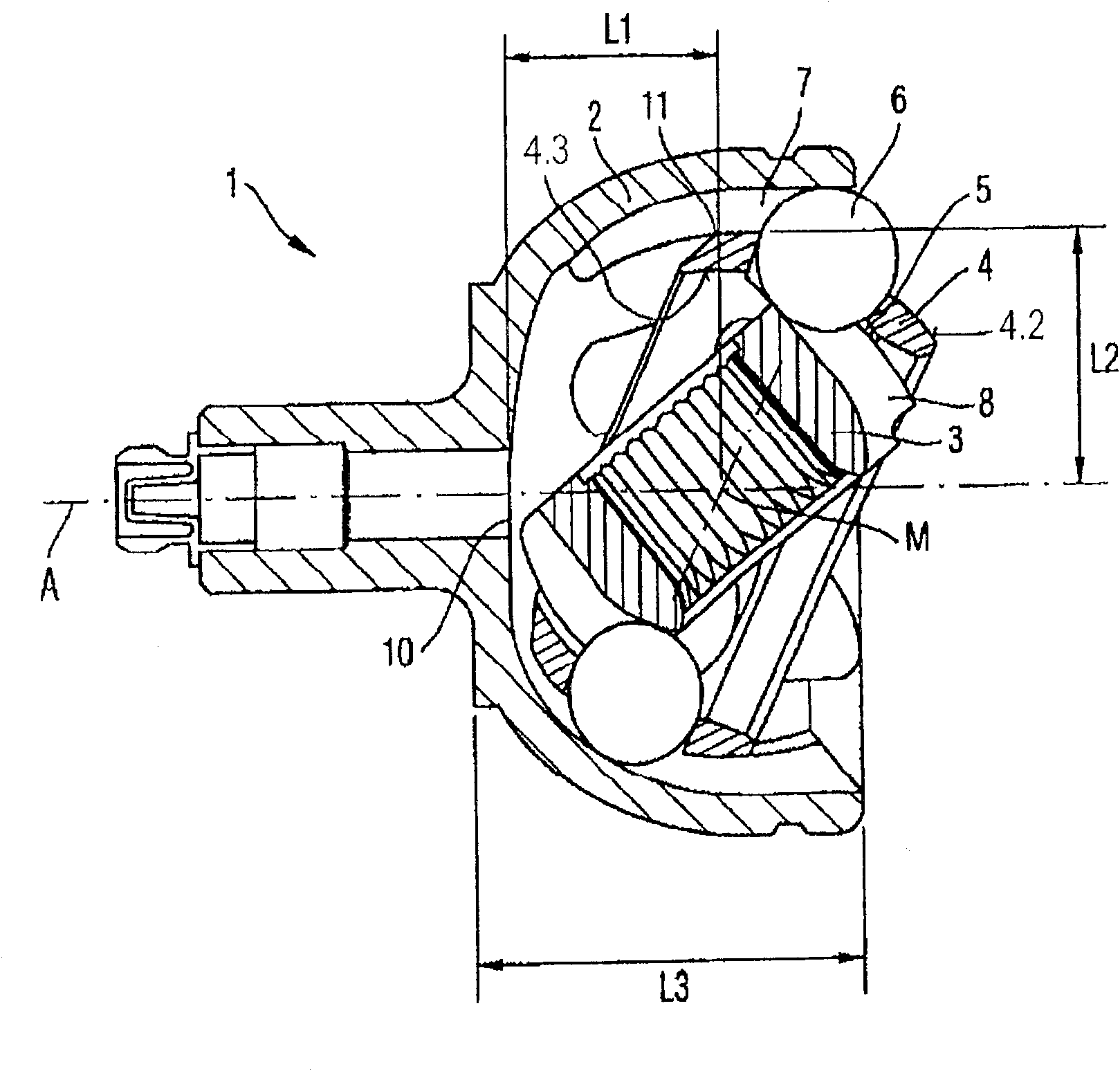
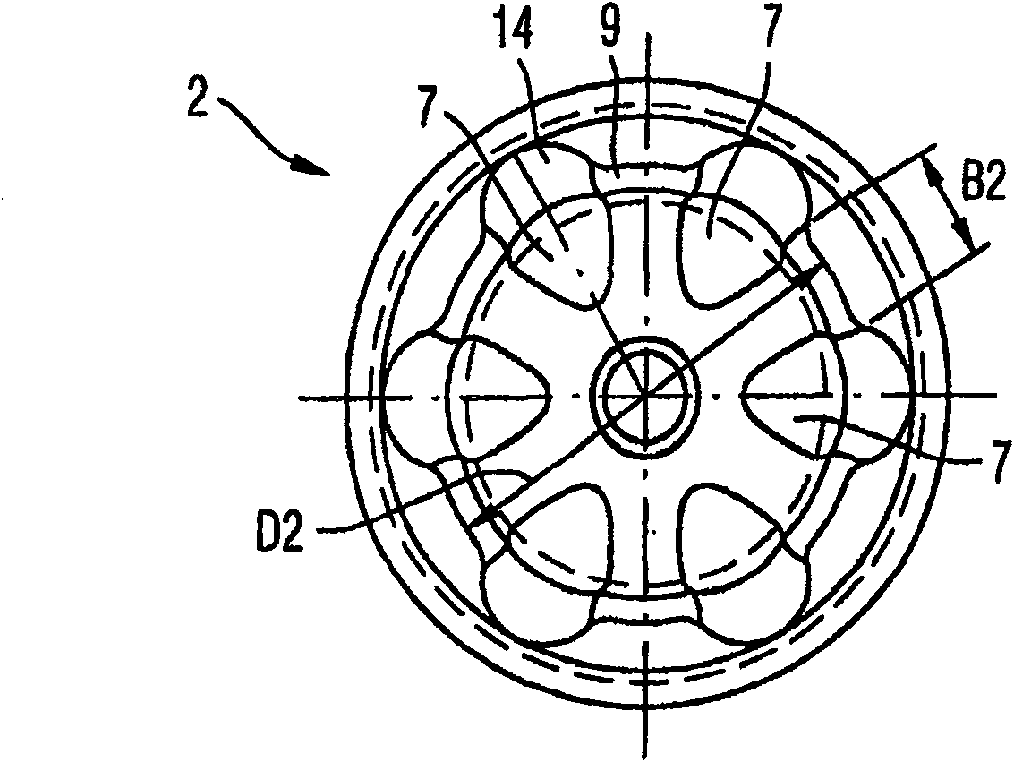
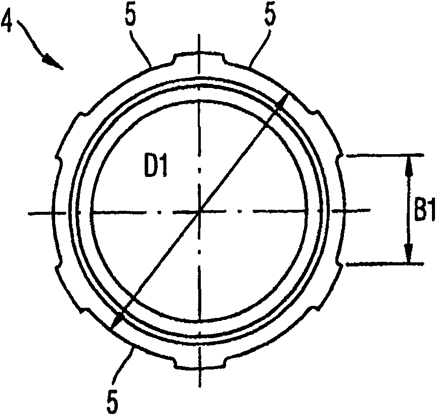
[0041] Figures 1 to 6 The first embodiment shown in shows a synchronous joint 1 for torque transmission with angular balance. The synchronous joint 1 comprises an outer part 2 of bell-shaped design shown here by way of example, an inner part 3 accommodated in the outer part and a cage 4 which can surround a center point M of rotation. It is held pivotally between the outer part 2 and the inner part 3 . For this purpose, spherically curved surfaces 4 . 2 and 4 . 3 are provided on the cage outside and cage inside, which can be slidably guided on corresponding wall sections of the outer part 2 and inner part 3 , respectively. The centers of curvature of the outer surface 4.2 and the inner surface 4.3 are located at the midpoint M of rotation. Although a small axial offset of the above-mentioned center of curvature is possible, such an eccentricity cannot be used to control the ball 6 in the half-angle plane. A plurality of windows 5 distributed in the circumferential directio...


PUM


Abstract

A constant velocity joint (1) comprises an outer part (2), an inner part (3) and a full cage (4), which is accommodated while holding itself between these parts and which is provided with windows (5) for holding balls (6) inside races (7, 8) on the outer part (2) and on the inner part (3). The cage (4) is guided around a common center of curvature (M) via spherical outer surfaces (4.2) on the outer part (2) and via spherical inner surfaces (4.3) on the inner part (3). During assembly, the outer part (2) and the cage (4) can be slid inside one another in the direction of the parts axes thereof. This permits a particularly compact design of constant velocity joints (1) with Stuber offset. Special recesses on the outer part (2) enable the balls (6) to be inserted when the inner part (3) is already connected to a shaft. The invention also relates to an assembly method for a joint of the aforementioned type.

Description

technical field [0001] The invention relates to a synchronous articulated joint (Gleichlauffestgelenk) with an outer part, an inner part and a full cage (Vollkaefig) held in a self-sustaining manner between the outer part and the inner part, the cage having a window (Fester) for retaining balls in raceways on outer and inner parts, wherein the full cage surrounds a common curvature with a spherical outer surface on the outer part and a spherical inner surface on the inner part Guided in the center, the outer part and the cage are displaceable relative to each other in the direction of their component axis during assembly. Furthermore, the invention relates to an assembly method for such a joint. Background technique [0002] For the purposes of the present application, said concentricity also includes only small axial deviations of the center of curvature. Of course, this deviation is not as preferentially used for the control of the hinged joint as it is on the double ecc...

Claims


Application Information

Patent Timeline
Patent Type & Authority Patents(China)
IPC IPC(8): F16D3/223F16D3/2237
CPCF16D2003/22303Y10S464/906F16D3/2237
Inventor G·沙夫G·凯泽
Owner VOLKSWAGEN AG
Why Eureka
Try Eureka