
Linear motor system

a technology of linear motors and parallel rails, applied in the direction of mechanical energy handling, dynamo-electric machines, supports/encloses/casings, etc., can solve the problems of limiting the life of the motor, affecting affecting the alignment of parallel rails of this type, so as to facilitate the linear motion of the magnet assembly, and prevent moisture and/or chemical ingress

Active Publication Date: 2012-08-02
ROCKWELL AUTOMATION
View PDF10 Cites 2 Cited by
  • Summary
  • Abstract
  • Description
  • Claims
  • Application Information

AI Technical Summary

Benefits of technology

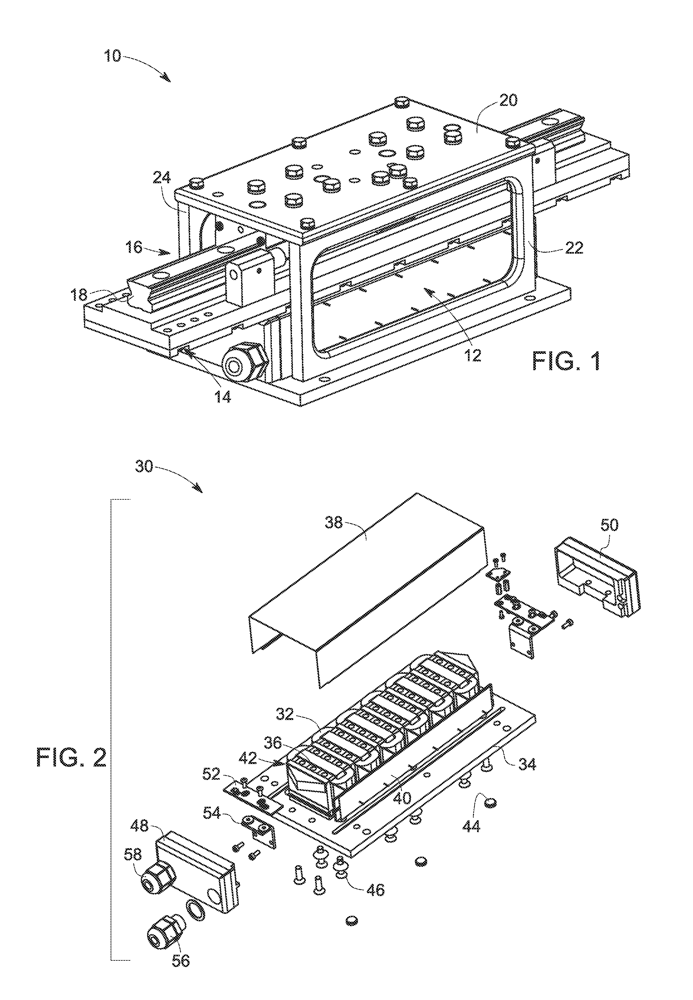
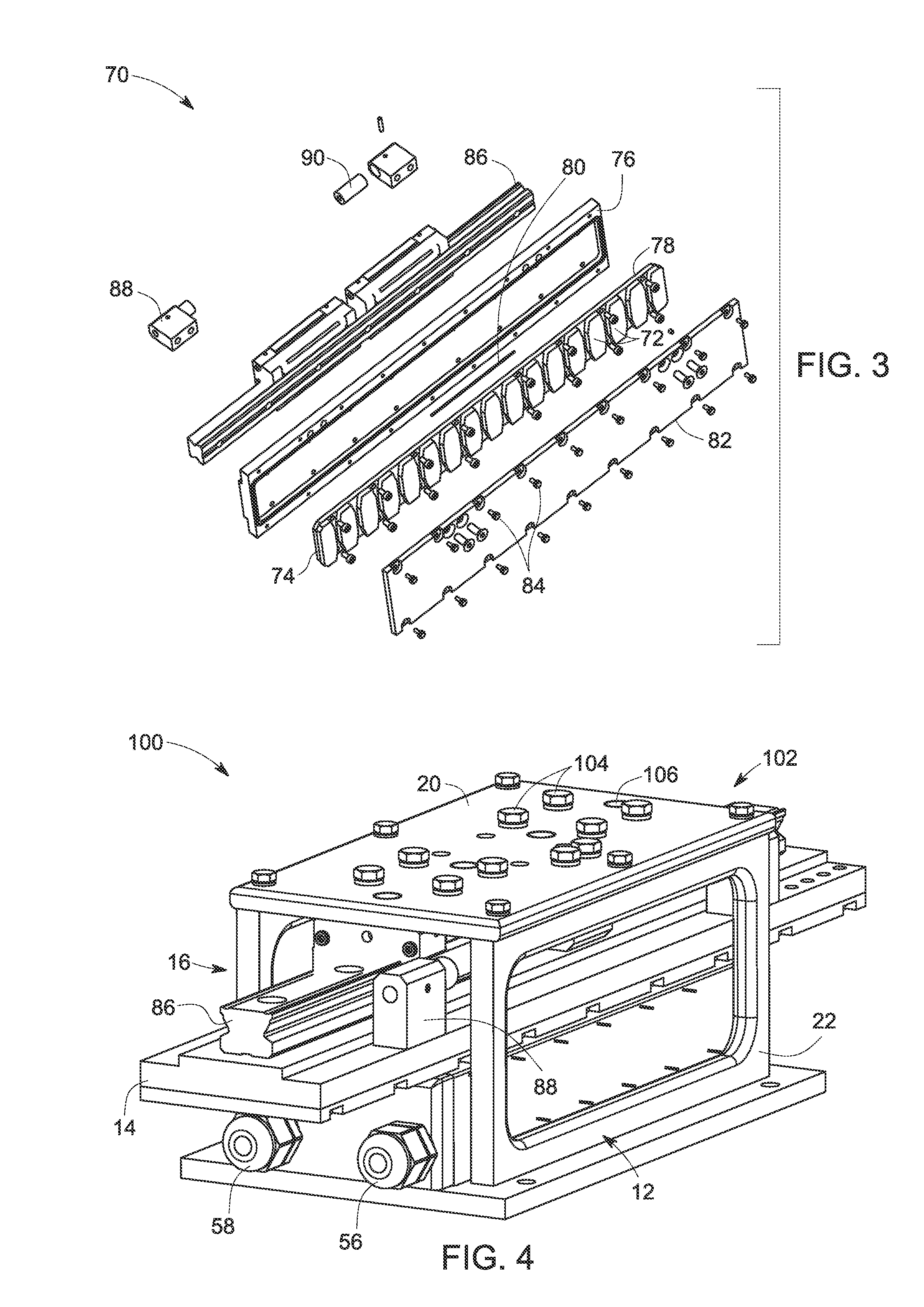
"The present invention provides a sealed linear motor system that includes a sealed coil assembly and a sealed magnet assembly. The sealed coil assembly has a plurality of coil windings within a base plate and includes covers to prevent moisture and chemical ingress. The sealed magnet assembly has a plurality of magnets mounted on a magnet mounting plate and a magnet housing to cover and seal the magnets. The sealed linear motor system also includes a motor stage structure and a bearing assembly to facilitate linear motion of the magnet assembly. The sealed linear motor system further includes at least one encoder sensor sealed within the coil assembly to sense position and motion information of the magnet assembly. The technical effects of the sealed linear motor system include prevention of moisture and chemical ingress, improved protection of components, and improved accuracy and reliability of position and motion sensing."

Problems solved by technology

In certain applications, the linear motor systems may be subjected to loads that may cause stresses on alignment structures of the motor systems.
For example, side loading may occur that can cause bearings to exert forces on guide rails and other structures in ways that may lead to early wear and limit the life of the motors.
Careful alignment of parallel rails of this type can be demanding during manufacturing and assembly.

Method used


Image

  • Linear motor system
  • Linear motor system
  • Linear motor system

Examples


Embodiment Construction

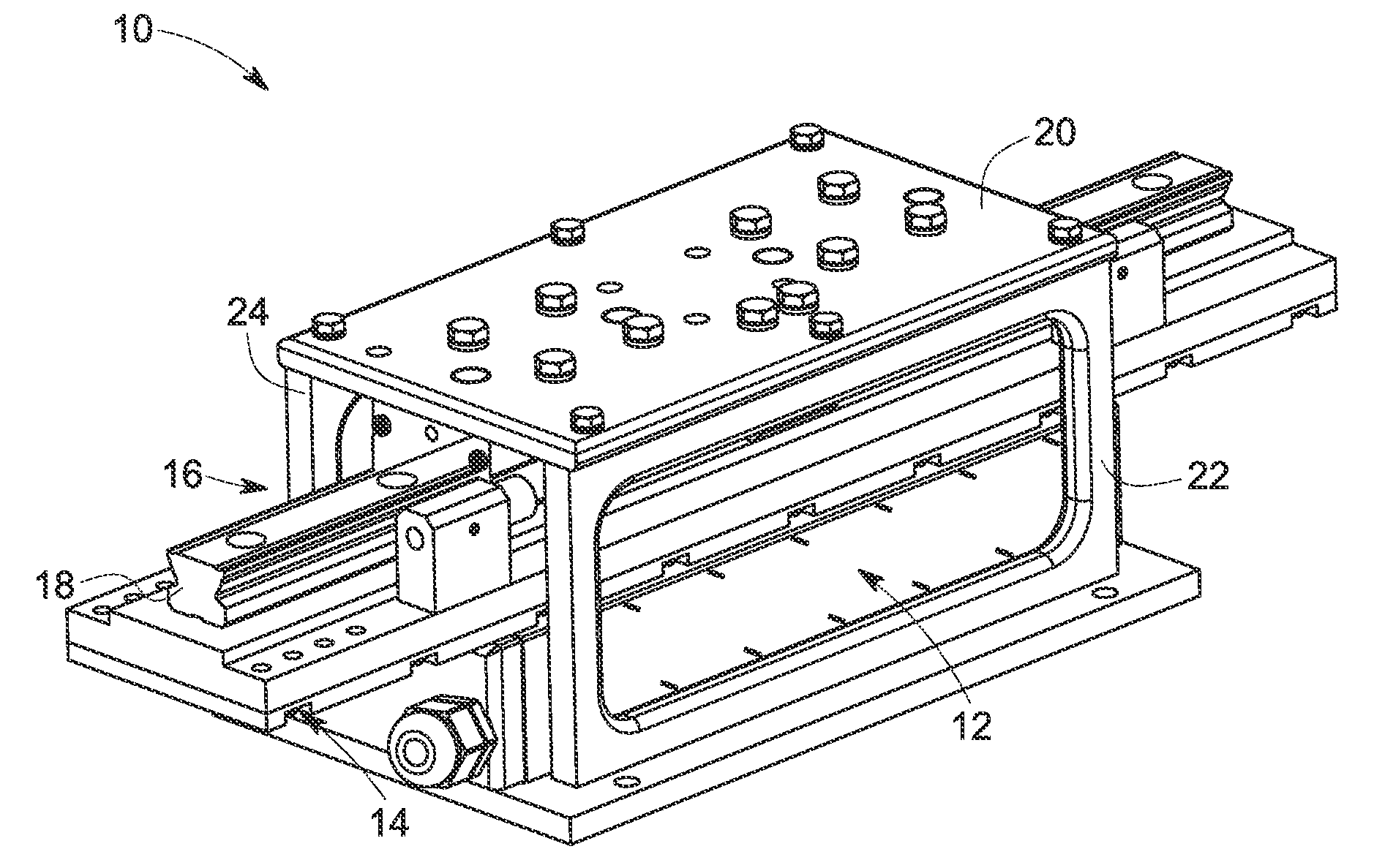
[0016]As discussed in detail below, embodiments of the present technique function provide a sealed linear motor system for use in applications such as food processing applications, wet installations and chemical laden environments. In particular, the sealed linear motor system includes individually sealed coil and magnet assemblies to prevent moisture and / or chemical ingress within the system.

[0017]References in the specification to “one embodiment”, “an embodiment”, “an exemplary embodiment”, indicate that the embodiment described may include a particular feature, structure, or characteristic, but every embodiment may not necessarily include the particular feature, structure, or characteristic. Moreover, such phrases are not necessarily referring to the same embodiment. Further, when a particular feature, structure, or characteristic is described in connection with an embodiment, it is submitted that it is within the knowledge of one skilled in the art to affect such feature, struc...


PUM


Abstract

A linear motor system is provided includes a coil assembly, a magnet assembly, and a bearing assembly disposed between the coil and magnet assemblies to allow movement of one or both of them. The bearing assembly includes a single bearing rail that can be mounted on either side of the magnet assembly. The rail has elongated recesses that receive bearing elements. A stage structure may be attached to the assembly, such at to the magnet assembly, to move a machine component along the rail.

Description

CROSS REFERENCE TO RELATED APPLICATIONS[0001]This application is a continuation of U.S. patent application Ser. No. 12 / 789,320, entitled “Sealed Linear Motor System”, filed May 27, 2010, which is herein incorporated by reference.BACKGROUND[0002]The invention relates generally to linear motors, and particularly to a linear motor system with a single bearing rail for ease of assembly and improved performance.[0003]Linear motors are known in the art and are used in a variety of applications such as machining, robotic positioning and food processing and packaging applications. One type of a linear motor system includes stationary armatures having coils and movable stages containing magnets. Typically, the armature windings may be mounted to a base plate and a stage with a series of magnets is free to move on the base plate. The stage is guided in a desired direction by applying AC or DC excitation to the coils. Another type of linear motor system includes stationary magnets and moving c...

Claims


Application Information

Patent Timeline
Patent Type & Authority Applications(United States)
IPC IPC(8): H02K41/03
CPCH02K5/10H02K5/225H02K5/16H02K41/031H02K41/02H02K7/08
Inventor LAMOUREE, JOHNSOMMERHALTER, FREDBOBELIS, DARIUS
Owner ROCKWELL AUTOMATION
Learn More