
Powered surgical instrument having a transmission system

a transmission system and surgical instrument technology, applied in the field of powered surgical instruments having transmission systems, can solve the problems of incomplete firing, inability to effectively form closed staples in severed tissue, and the complexity and function of endoscopic staplers/cutters continue to increas

Active Publication Date: 2013-07-25
CILAG GMBH INT
View PDF0 Cites 404 Cited by
  • Summary
  • Abstract
  • Description
  • Claims
  • Application Information

AI Technical Summary

Benefits of technology

The present patent application is a continuation of several related patent applications filed in July 2007 and is about a surgical instrument with wireless communication between a control unit and sensors. The patent application describes various improvements made to the instrument, including the ability to close upon tissue before firing, the use of a single firing stroke to simultaneously sever and staple tissue, and the incorporation of interlocks to prevent reuse of the instrument. The patent text also mentions the development of endoscopic surgical instruments that are suitable for precise placement of a distal end effector at a desired surgical site through a cannula of a trocar. These instruments engage tissue in a variety of ways to achieve a diagnostic or therapeutic effect. The patent text highlights the increasing complexity and function of endoscopic staplers / cutters and the need for improved instruments for endoscopic surgery.

Problems solved by technology

Otherwise, opposing jaws may be drawn too close together, especially pinching at their distal ends, and thus not effectively forming closed staples in the severed tissue.
At the other extreme, an excessive amount of clamped tissue may cause binding and an incomplete firing.
Endoscopic staplers / cutters continue to increase in complexity and function with each generation.
These devices have not faired much better than traditional hand-powered devices, but for a different reason.
One challenge in using such electronics in a surgical instrument is delivering power and / or data to and from the sensors, particularly when there is a free rotating joint in the surgical instrument.

Method used


Image

  • Powered surgical instrument having a transmission system
  • Powered surgical instrument having a transmission system
  • Powered surgical instrument having a transmission system

Examples


Embodiment Construction

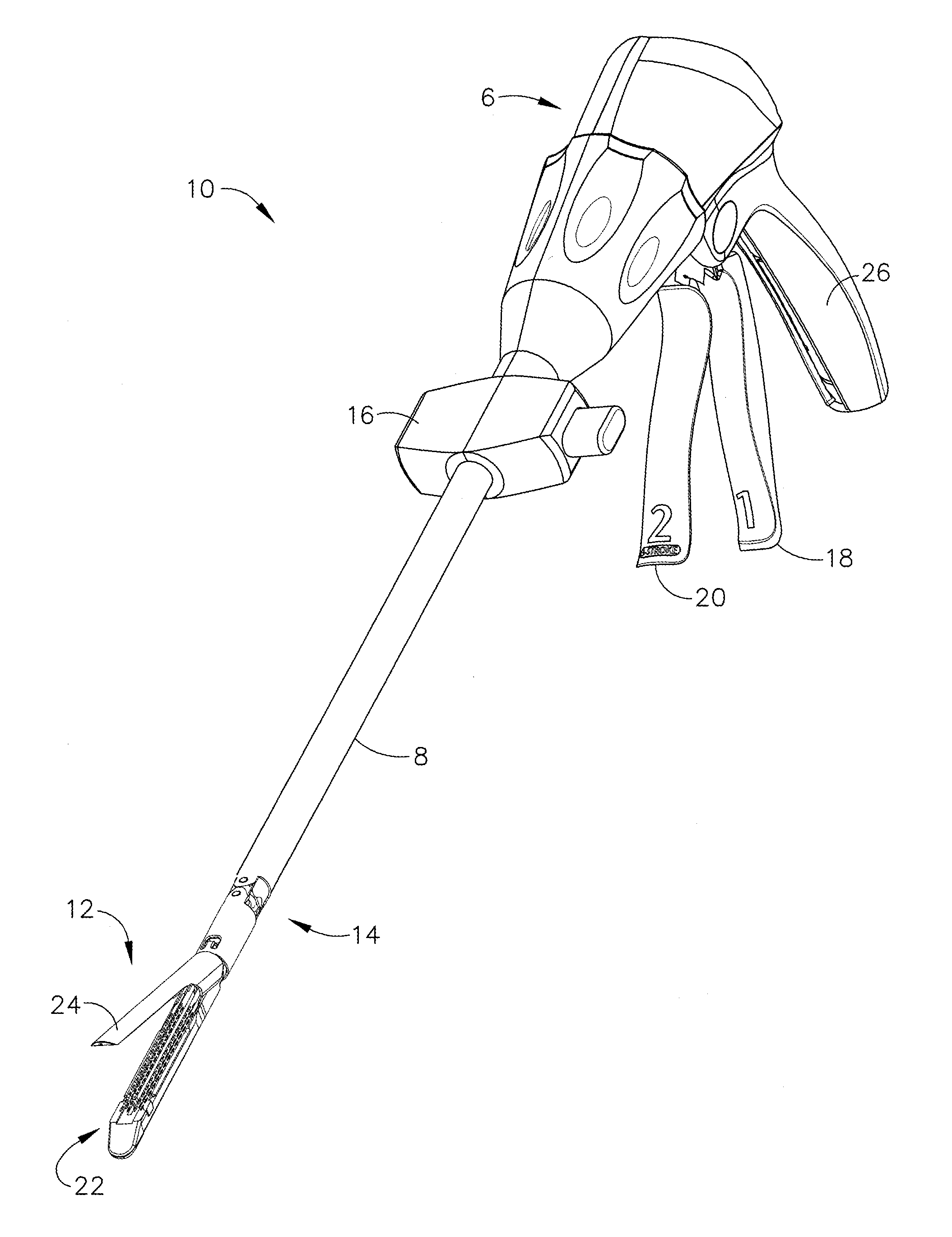
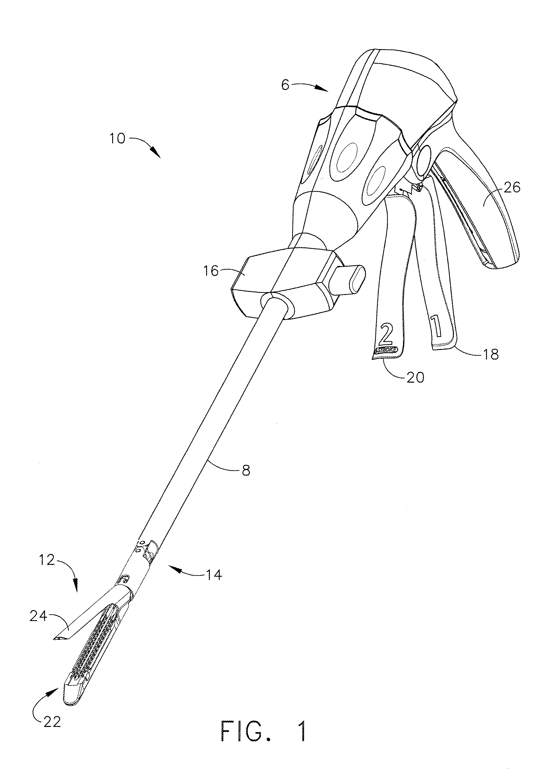
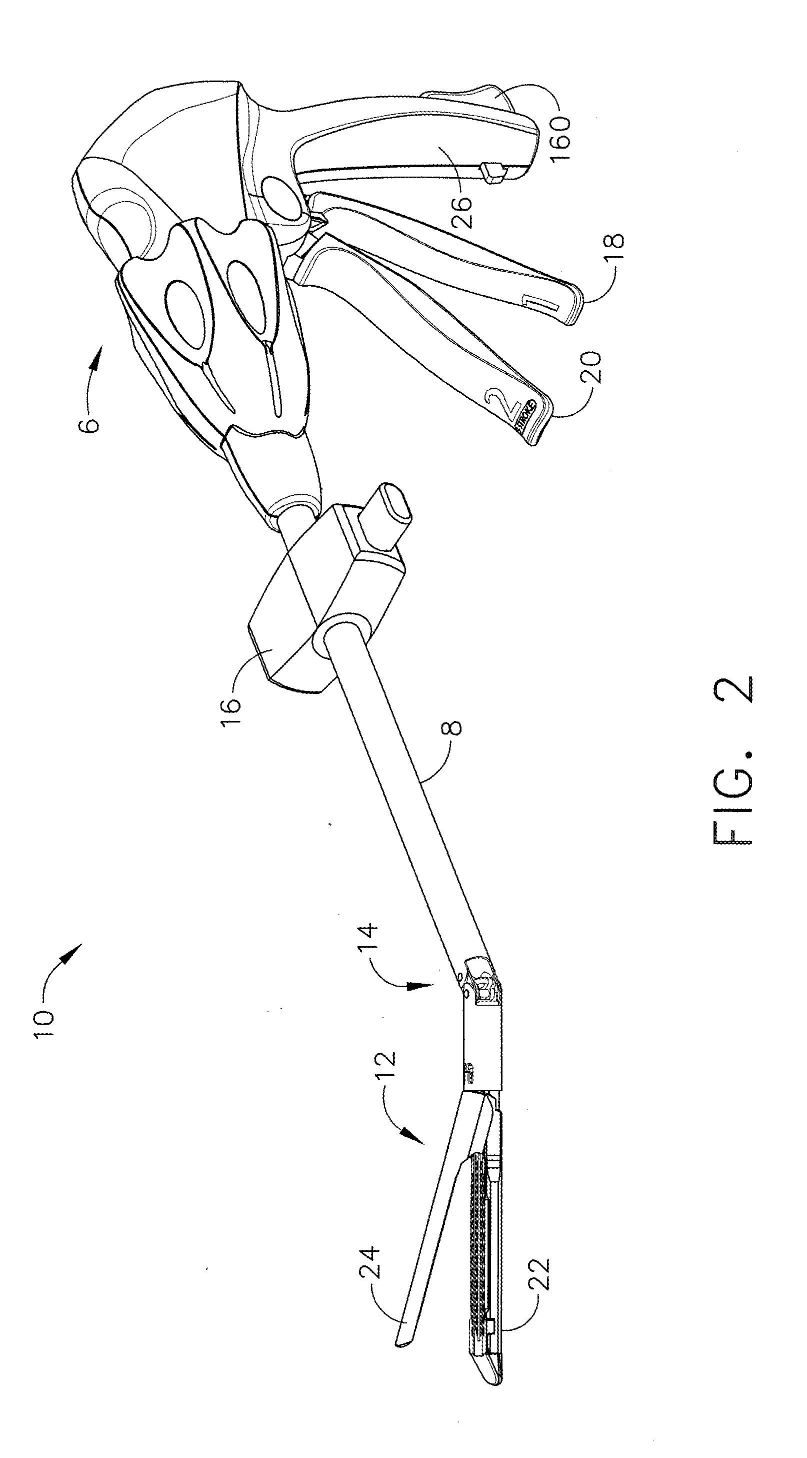
[0029]Various embodiments of the present invention are directed generally to a surgical instrument having at least one remote sensor transponder and means for communicating power and / or data signals to the transponder(s) from a control unit. The present invention may be used with any type of surgical instrument comprising at least one sensor transponder, such as endoscopic or laparoscopic surgical instruments, but is particularly useful for surgical instruments where some feature of the instrument, such as a free rotating joint, prevents or otherwise inhibits the use of a wired connection to the sensor(s). Before describing aspects of the system, one type of surgical instrument in which embodiments of the present invention may be used—an endoscopic stapling and cutting instrument (i.e., an endocutter)—is first described by way of illustration.

[0030]FIGS. 1 and 2 depict an endoscopic surgical instrument 10 that comprises a handle 6, a shaft 8, and an articulating end effector 12 pivo...


PUM


Abstract

A powered surgical apparatus for engaging tissue includes a housing assembly and a movable portion operatively connected to the housing assembly. The movable portion is movable with respect to the housing assembly. In addition, the surgical apparatus includes a power source configured to supply electrical power, and a transmission system configured to transfer at least one of a signal and electrical power between the handle assembly and the movable portion, the transmission system including a first electronic board disposed in the handle assembly and a second electronic board positioned in the movable portion, the second electronic board including a primary control circuit and a secondary control circuit wherein the movable portion is configured and adapted to rotate about a longitudinal axis defined by the powered surgical apparatus.

Description

CROSS REFERENCE TO RELATED APPLICATIONS[0001]The present application is a continuation of U.S. patent application Ser. No. 11 / 651,715, filed, Jan. 10, 2007, entitled “SURGICAL INSTRUMENT WITH WIRELESS COMMUNICATION BETWEEN CONTROL UNIT AND SENSOR TRANSPONDERS”, now U.S. Patent Publication No. 2008-0167522 A1, the entire disclosure of which is hereby incorporated by reference herein.[0002]The present application is related to the following U.S. patent applications, which are incorporated herein by reference:[0003](1) U.S. patent application Ser. No. 11 / 651,807 entitled “SURGICAL INSTRUMENT WITH WIRELESS COMMUNICATION BETWEEN CONTROL UNIT AND REMOTE SENSOR,” by J. Giordano et al., now U.S. Patent Publication No. 2008-0167672 A1;[0004](2) U.S. patent application Ser. No. 11 / 651,806 entitled “SURGICAL INSTRUMENT WITH ELEMENTS TO COMMUNICATE BETWEEN CONTROL UNIT AND END EFFECTOR,” by J. Giordano et al., now U.S. Patent Publication No. 2008-0167671 A1;[0005](3) U.S. patent application Ser...

Claims


Application Information

Patent Timeline
IPC IPC(8): A61B17/00
CPCA61B17/00234A61B2560/0266A61B19/026A61B2017/00022A61B2017/00039A61B2017/00212A61B2017/00221A61B2017/00362A61B2017/00398A61B2017/00734A61B2017/0688A61B2017/07214A61B2017/2927A61B2017/320052A61B2019/0267A61B2019/0286A61B2019/448A61B2019/465A61B2019/4857A61B17/00A61B17/068A61B17/07207A61B2050/314A61B2050/3015A61B50/30A61B90/98A61B2090/065A61B2090/0811
Inventor GIORDANO, JAMES R.SHELTON, IV, FREDERICK E.SWAYZE, JEFFREY S.
Owner CILAG GMBH INT
Learn More