Low voltage rigid cable

a low-voltage, rigid cable technology, applied in the direction of machine supports, coupling device connections, domestic objects, etc., can solve the problems of low high risk of electric shock, and inconvenient rigid cable us

Inactive Publication Date: 2013-08-01
TP24
View PDF4 Cites 4 Cited by
  • Summary
  • Abstract
  • Description
  • Claims
  • Application Information

AI Technical Summary

Benefits of technology

[0023]in the event of a fault, the earth conductor directs any elec...

Problems solved by technology

Since the neutral conductor is exposed and the rigid cable does not comprises any means to protect a user from an electric shock, this particular rigid cable is only suitable for transferring an extra-low voltage, where the voltage rating is less than 50V AC and the risk of electric shock is low.
The rigid cab...

Method used


Image

  • Low voltage rigid cable
  • Low voltage rigid cable
  • Low voltage rigid cable

Examples


third embodiment

A5. Third Embodiment of the Rigid Cable

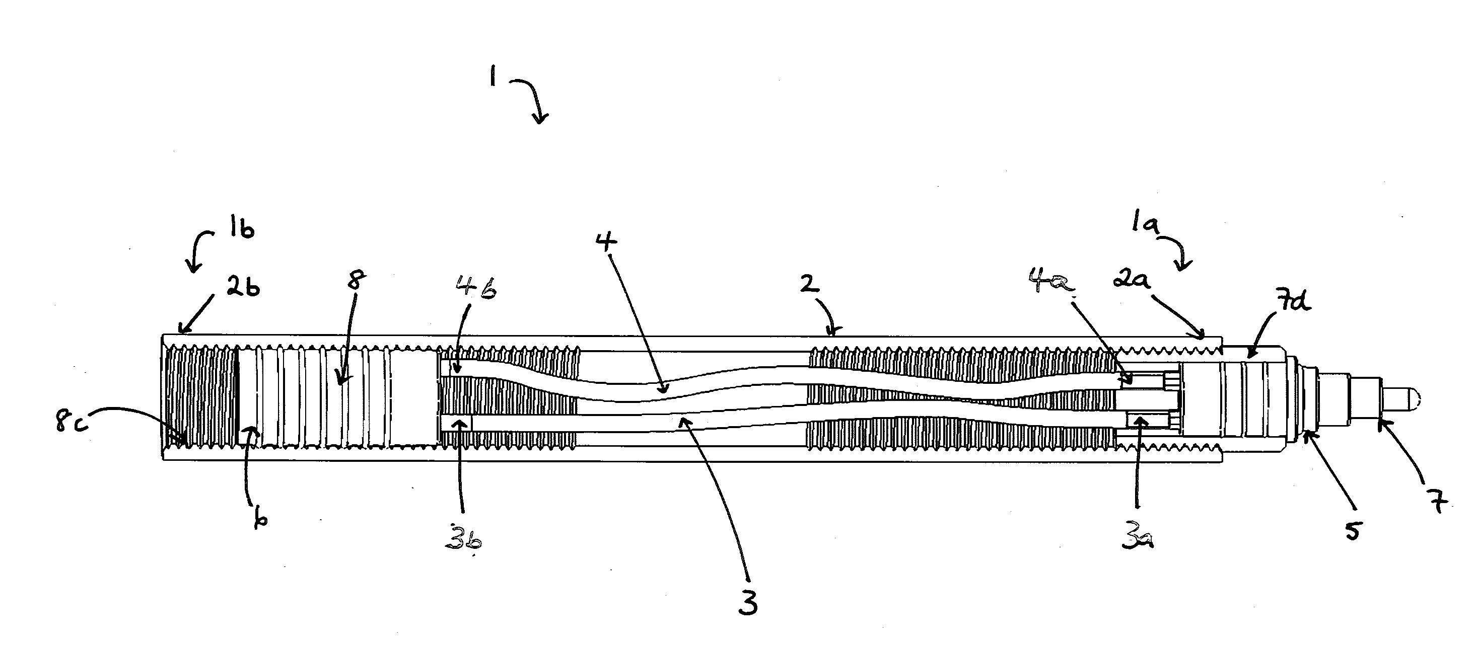
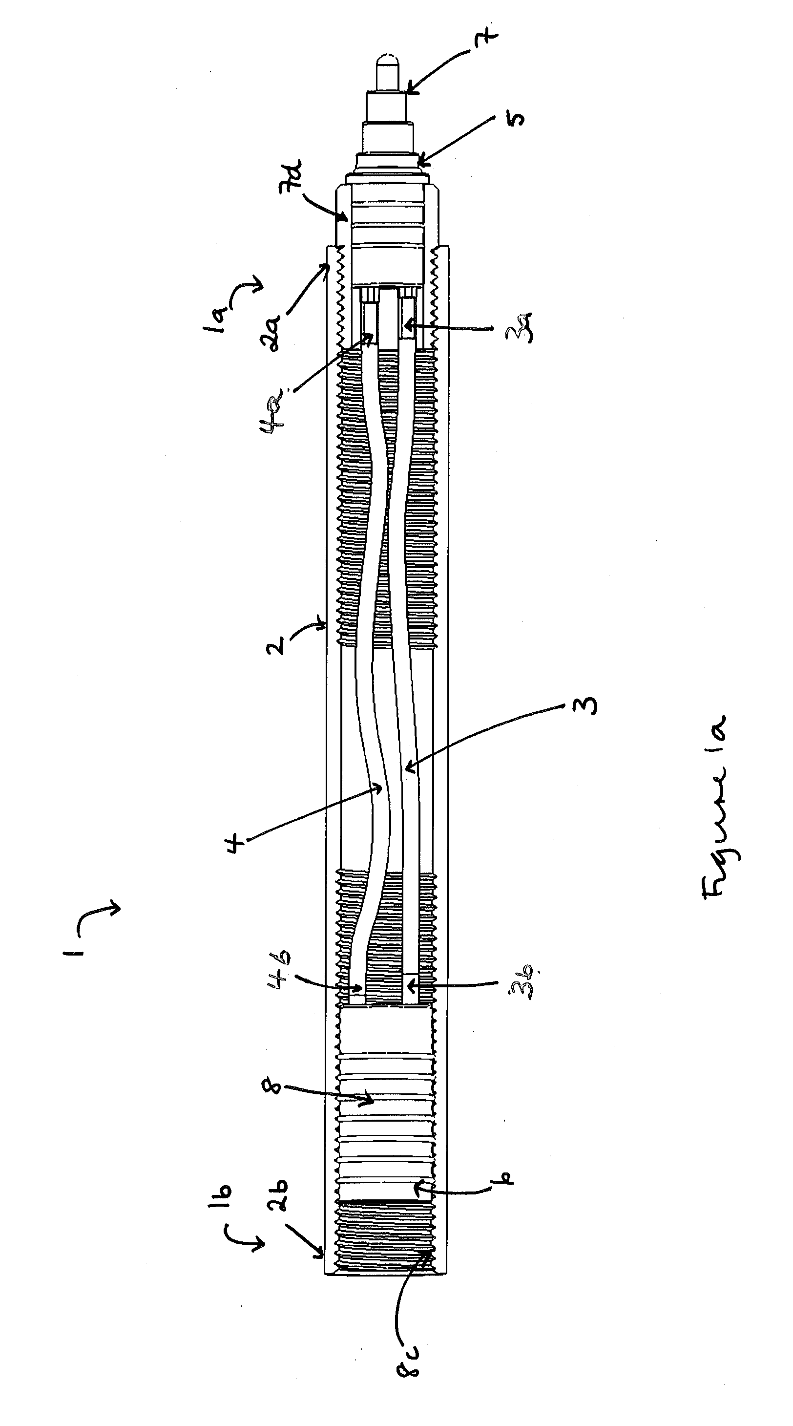
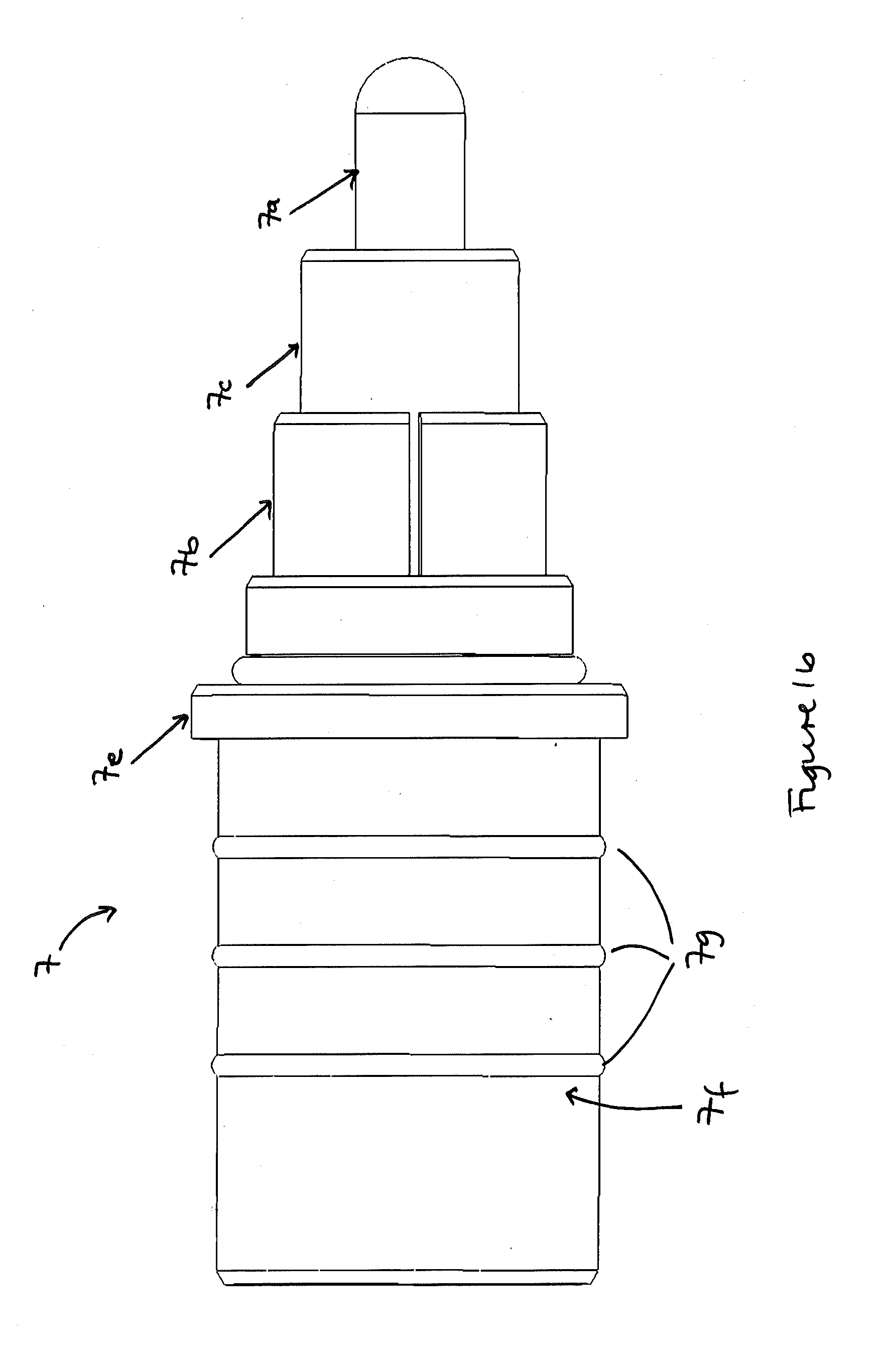
[0119]FIGS. 3a-3d depict a third embodiment of the rigid cable whereby the releasable male coupling means comprises a plug portion (7) and a collar (12) comprising an internal screw thread portion (13).

[0120]The male coupling means of the rigid cable is configured to be coupled to the complementary female coupling means of another member. In the embodiment depicted in FIGS. 3a-3d, the rigid cable is configured to be coupled to a mounting unit (MU) comprising a complementary female coupling means.

[0121]The plug portion of the male coupling means comprises a central pin contact (7a) (the live contact) coupled to the first end of the live conductor (3a), an annular contact (7b) (the neutral contact) coupled to the first end of the neutral conductor (4a) and an earth contact (7d) coupled to the housing (earth conductor). The central pin live contact, annular neutral contact and annular earth contact are coaxially arranged, in a stepped formation. T...

fourth embodiment

A6. Fourth Embodiment of the Rigid Cable

[0128]FIG. 4 depicts a fourth embodiment of the rigid cable, whereby a rigid cable (1) according to a first aspect of the invention is configured to be coupled to a light source (LS) so as to form a lighting assembly (L).

[0129]The rigid cable comprises a male coupling means (5) arranged at a first end of the rigid cable (1a) and a female coupling means (not shown) arranged at a second end of the rigid cable. The male coupling means is a releasable male coupling means as depicted in FIGS. 2a-2f. The female coupling means is configured to couple the rigid cable and a light source. The female coupling means may be configured to releasably or permanently couple the rigid cable and the light source.

[0130]The rigid cable may be configured to be coupled to any suitable light source. For example, the female coupling means may be configured to engage a low energy light source such as a CFL or LED.

[0131]The rigid cable may be configured to be coupled wi...

first embodiment

B1. First Embodiment of a Lighting System

[0146]FIGS. 5a and 5b depict a first embodiment of a lighting system that is suitable for mounting on a ceiling. The lighting system comprises a ceiling rose (C) and multiple arms (A).

[0147]The ceiling rose is configured to be mechanically coupled to a ceiling and electrically coupled to a mains power supply. Each arm is configured to be mechanically and electrically coupled to the ceiling rose and a lamp assembly (L) so that it can support and distribute an electrical current to the light source of the lamp assembly.

[0148]Each arm (A) is a rigid cable according to a first aspect of the invention. In the embodiment depicted in FIGS. 5a and 5b, the arms are configured to extend downwardly from the ceiling rose. The first end of each arm is configured to be mechanically and electrically coupled to the ceiling rose. A second end of each arm is configured to be mechanically and electrically coupled to a lamp assembly.

[0149]As shown in FIGS. 5a an...


PUM


Abstract

A first aspect of the invention relates to a low voltage rigid cable comprising a substantially rigid housing, a live conductor arranged within the housing, a neutral conductor arranged within the housing, a first coupling means to couple the rigid cable with a first member, a second coupling means configured to couple the rigid cable with a second member and protection means to protect against electric shock. The protection means may comprise an earth conductor and insulating means configured to form an insulating barrier between the conductive parts of the rigid cable. In an embodiment of the invention, the housing may be configured to form an earth conductor. Further aspects of the invention relate to a rigid cable structure.

Description

FIELD OF INVENTION[0001]This disclosure relates to a rigid cable with a low voltage rating. The disclosure also relates to a rigid cable structure comprising at least one rigid cable. Moreover, the disclosure relates to a lighting system comprising one or more of the rigid cables.BACKGROUND TO THE INVENTION[0002]A rigid cable is understood to be an electric cable having a substantially rigid construction.[0003]Due to its rigid construction, a rigid cable is able to substantially maintain its shape under an applied load. For this reason, rigid cables have been used to both support and transfer electrical current to an electrical device.[0004]UK Patent Application No 89076739.1 describes a lighting system comprising one or more rigid cables. The configuration of the lighting system may be changed by adding or removing rigid cables. The rigid cable comprises an internal live conductor, an external neutral conductor and coupling means to secure the rigid cable end-to-end with other cabl...

Claims


Application Information

Patent Timeline
IPC IPC(8): F21V21/10H02G15/00
CPCF21V21/12H01B13/004H01R24/38H01R25/003H01R2103/00F21V21/10F21Y2101/02F21S2/005F21S8/065F21V21/002F21V21/02F21V23/06H02G15/00F21Y2115/10H01B7/16
Inventor DAVIS, SHAUN
Owner TP24
Why Eureka
Try Eureka