
Leaf seal

a technology of leaf and seal, applied in the direction of engine seals, engine components, machines/engines, etc., can solve the problems of increasing leakage, increasing the configuration of blowing down, and accelerating leaf wear

Inactive Publication Date: 2013-08-08
ROLLS ROYCE PLC
View PDF18 Cites 7 Cited by
  • Summary
  • Abstract
  • Description
  • Claims
  • Application Information

AI Technical Summary

Benefits of technology

The patent describes a seal design that can control the width of the gap between two parts to reduce or eliminate torque and also to control the amount of blow-down (when air escapes) during operation. The seal uses flexible cover plates that deflect under differential pressure to control the gap width and apply the necessary retarding torque on the other component. The ratio of the cover plate to the part is important for flexibility and to allow for changes in blow-down with changing differential pressure. Overall, the seal design improves the performance and efficiency of the sealing process in various applications.

Problems solved by technology

Excessive blow-down can lead to accelerated leaf wear and excessive blow-up leads to increased leakage.
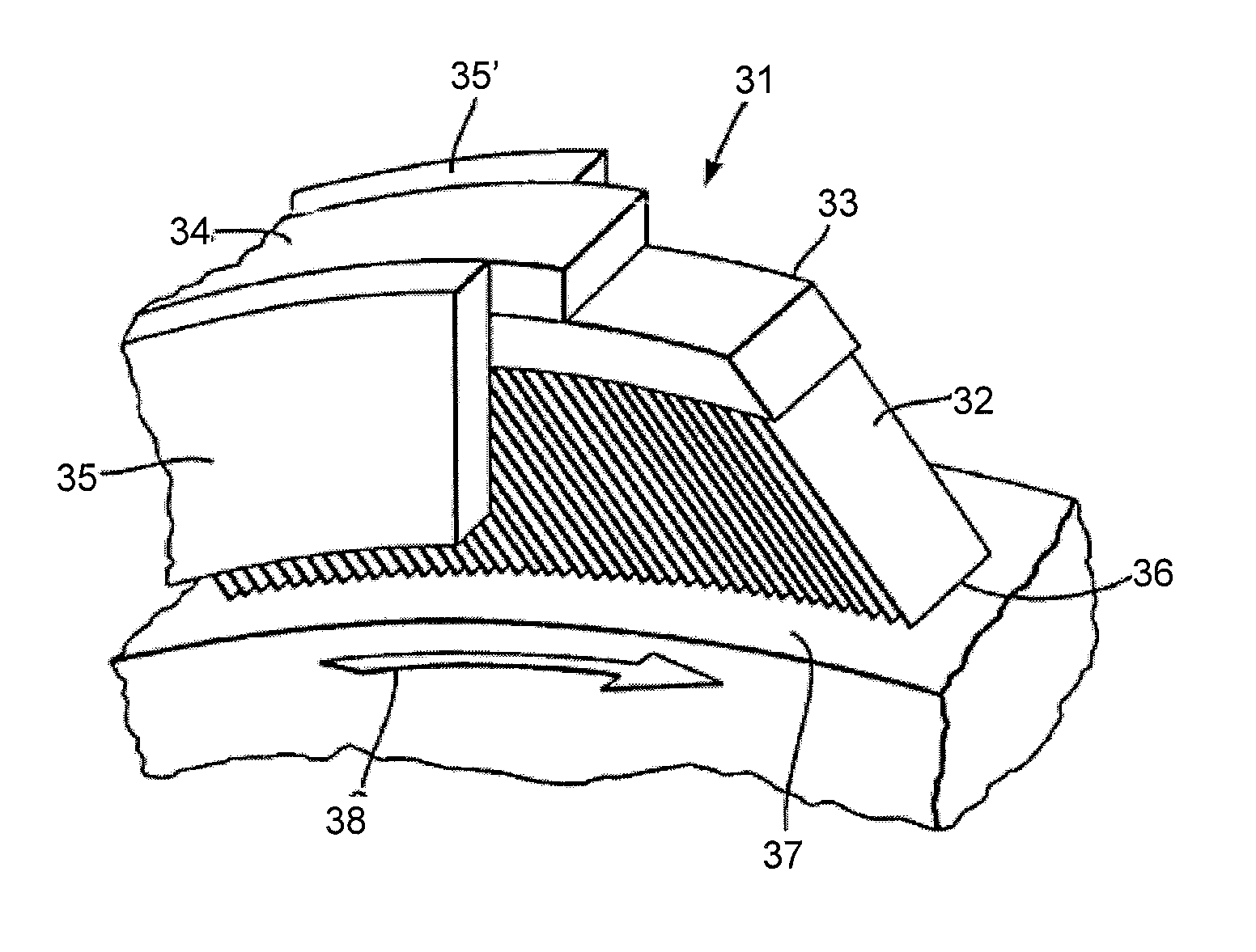
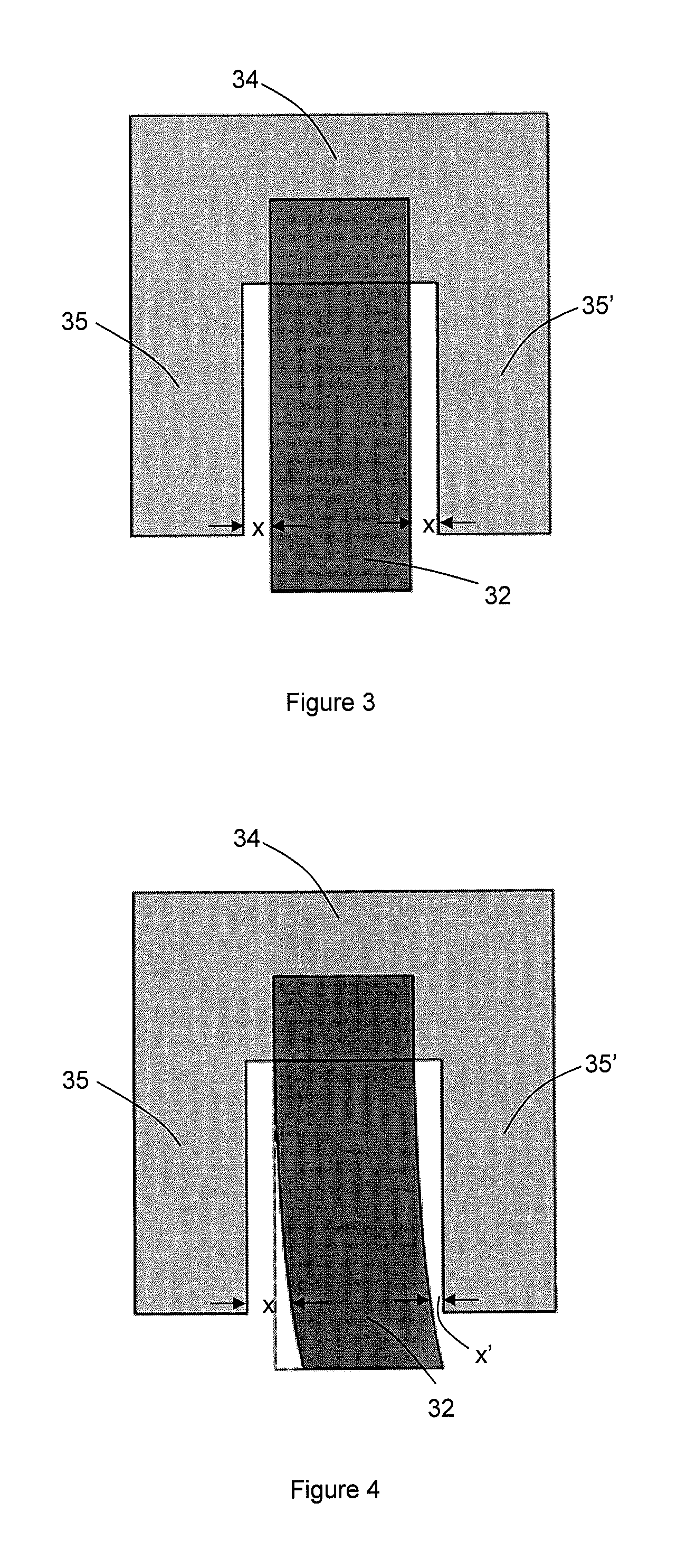
Thus the front gap x opens up and the rear gap x′ closes up, most significantly at the edges of the coverplates proximal the leaf edges, leading to an increasingly severe blow-down configuration (the blow-down increases much more than by the differential pressure alone).
As a result, at the very pressures where large rotor contact forces are generally not desirable, the leaf seal imparts a large torque due to the high differential pressure across the leaf seal which is made significantly worse by the elevated blow-down configuration of the coverplate to leaf pack gaps.
This significantly limits the maximum differential pressure that the leaf seal can be subjected to.

Method used


Image

  • Leaf seal
  • Leaf seal
  • Leaf seal

Examples


Embodiment Construction

[0050]Leaf seal assemblies according to the present invention may have coverplates which, by their flexibility, axially deflect under the application of the pressure to provide control of the axial gap between the coverplate and the adjacent leaf pack. For example, it is possible to match the axial deflection of the coverplate with the axial deflection of the leaf pack to ensure that the gap between the cover plate and leaf pack does not substantially depart from the nominal gap when a pressure condition is applied.

[0051]FIGS. 5(a) to (c) show schematically longitudinal cross-sections through the leaf pack and housing of leaf seal assemblies of respectively first to third embodiments of the present invention for sealing between an outer casing and a rotor shaft. Each leaf seal has a pack of leaves 132 secured in a housing comprising a backing ring 134 with upstream 135 and downstream 135′ coverplates. In FIG. 5(a), the front cover plate 135 is thinned so that it is flexible and axia...


PUM


Abstract

A leaf seal effects a seal between two, coaxial, relatively rotating components. The leaf seal has an annular pack of stacked leaves or a plurality of axially arranged annular packs of stacked leaves. The or each pack is mountable to one of the components with its leaves extending towards the other component such that the leaf edges of the pack are presented for wiping contact with the other component. The leaf seal further has upstream and downstream coverplates at the respective axial ends of the seal. Each coverplate is spaced from the adjacent annular pack by a respective axial gap. When viewed in the axial direction, each coverplate covers at least a portion of the radial extent of the adjacent pack. The upstream and / or the downstream coverplate is flexible to axially deflect under differential pressures which the seal experiences in operation.

Description

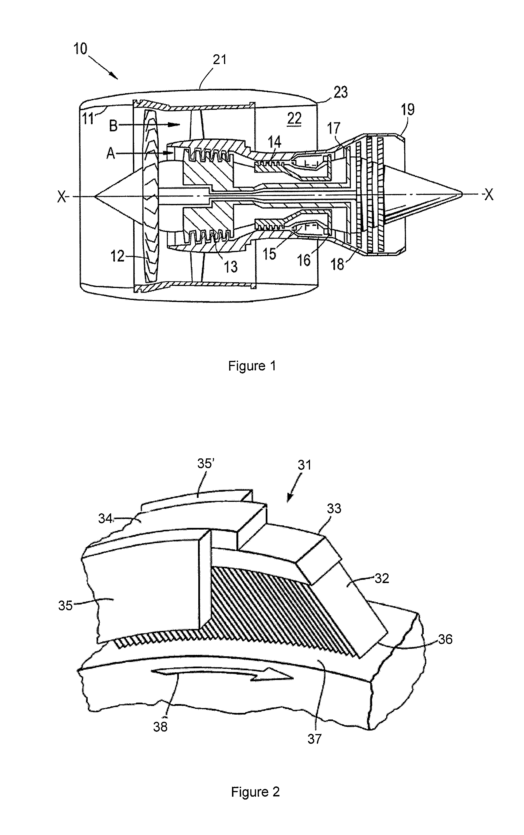
FIELD OF THE INVENTION[0001]The present invention relates to a leaf seal for effecting a seal between two coaxial, relatively rotating components.BACKGROUND OF THE INVENTION[0002]With reference to FIG. 1, a ducted fan gas turbine engine generally indicated at 10 has a principal and rotational axis X-X. The engine comprises, in axial flow series, an air intake 11, a propulsive fan 12, an intermediate pressure compressor 13, a high-pressure compressor 14, combustion equipment 15, a high-pressure turbine 16, and intermediate pressure turbine 17, a low-pressure turbine 18 and a core engine exhaust nozzle 19. A nacelle 21 generally surrounds the engine 10 and defines the intake 11, a bypass duct 22 and a bypass exhaust nozzle 23.[0003]The gas turbine engine 10 works in a conventional manner so that air entering the intake 11 is accelerated by the fan 12 to produce two air flows: a first air flow A into the intermediate pressure compressor 13 and a second air flow B which passes through t...

Claims


Application Information

Patent Timeline
IPC IPC(8): F02C7/28
CPCF16J15/3292F02C7/28
Inventor FRANCESCHINI, GERVAS
Owner ROLLS ROYCE PLC
Learn More