
Terminal and method for recognizing communication target

Inactive Publication Date: 2013-08-08
ELECTRONICS & TELECOMM RES INST +1
View PDF4 Cites 12 Cited by
  • Summary
  • Abstract
  • Description
  • Claims
  • Application Information

AI Technical Summary

Benefits of technology

This patent describes a method for easily selecting communication targets on a screen and establishing a communication link with them. The method involves displaying the location of communication targets in a different way to make them easier for the user to select. This can be done by adding a border between the communication targets or displaying them in a different order. The technical effect of this invention is to improve the user experience and facilitate communication targets selection.

Problems solved by technology

In addition, users are not able to obtain information about buildings and objects which are not present in the DB of the service providers.
Moreover, it is difficult to provide application services that allow the mutual transmission and reception of information between the user's terminal and other terminals in the proximity of the user based on location information of the other terminals.
Furthermore, in pattern matching scheme, in which an image captured by a user is compared with image patterns of objects stored in a DB as communication target candidates and a similarity therebetween is detected, the recognition of images may be difficult since the images are sensitive to lighting and weather conditions.

Method used


Image

  • Terminal and method for recognizing communication target
  • Terminal and method for recognizing communication target
  • Terminal and method for recognizing communication target

Examples


Embodiment Construction

[0038]The following detailed description is provided to assist the reader in gaining a comprehensive understanding of the methods, apparatuses and / or systems described herein. Various changes, modifications, and equivalents of the systems, apparatuses and / or methods described herein will suggest themselves to those of ordinary skill in the art. Descriptions of well-known functions and structures are omitted to enhance clarity and conciseness.

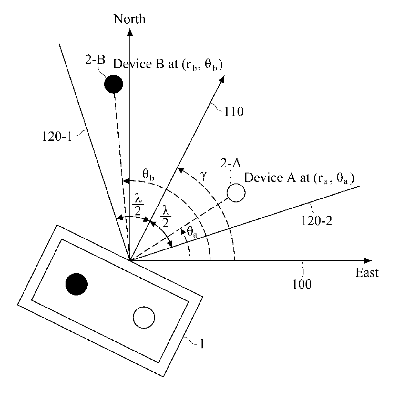
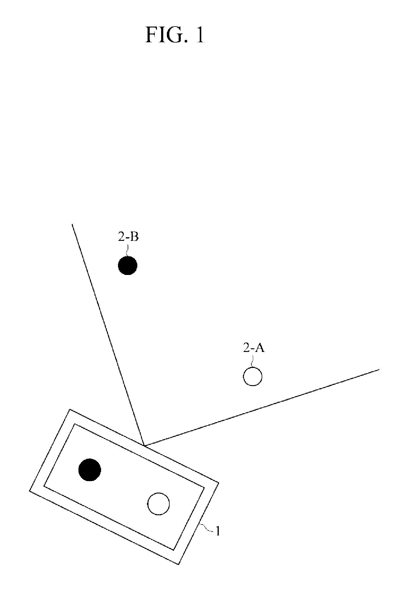
[0039]FIG. 1 is a diagram illustrating an example situation where communication target recognition of a user terminal is employed according to an exemplary embodiment of the present invention.

[0040]Referring to FIG. 1, a user terminal 1 (hereinafter, simply referred to as a “terminal”) uses location information of communication target candidates, device A 2-A and device B 2-B, which are located within a visible range of a user and in a direction in which the terminal 1 faces and identification information of each of which is unknown, to recogniz...


PUM


Abstract

A terminal and method for recognizing a communication target within a visible range. The method of a terminal to recognize a communication target includes obtaining location information of a communication target whose identification information is unknown within a visible range of a terminal user; and recognizing a relative location of the communication target with respect to the terminal based on the obtained location information and displaying the recognized relative location of the communication target.

Description

CROSS REFERENCE TO RELATED APPLICATION[0001]This application claims the benefit under 35 U.S.C. §119(a) of Korean Patent Application Nos. 10-2012-0012017, filed on Feb. 6, 2012, and 10-2013-0000746, filed on Jan. 3, 2013, the entire disclosures of which are incorporated herein by references for all purposes.BACKGROUND[0002]1. Field[0003]The following description relates to location recognition and location-based service provision.[0004]2. Description of the Related Art[0005]With the wide use of global positioning system (GPS)-equipped wireless terminals, such as smartphones, tablet PCs, and the like, an increasing number of various location-based services have been provided. Representative examples of such services are navigation systems that utilize coordinate information obtained in real time from signals from GPS satellites and augmented reality (AR) mobile applications that provide surrounding information. Recently, with the help of an access point (AP) of a wireless local area ...

Claims


Application Information

Patent Timeline
IPC IPC(8): H04W4/02
CPCH04W4/025
Inventor KANG, JOONHYUKKWAK, BYUNG-JAEKIM, YOUNG-HOONBANG, SEUNG-CHANPARK, EUNHYE
Owner ELECTRONICS & TELECOMM RES INST
Learn More