Tubular Heat Exchange

a technology of heat exchange and tubular structure, which is applied in the direction of indirect heat exchangers, machines/engines, lighting and heating apparatus, etc., can solve the problems of difficult and costly formation of exotic materials into complex shapes such as annular heat exchangers, and the environment of extreme temperature environments

Inactive Publication Date: 2013-08-15
QNERGY
View PDF8 Cites 3 Cited by
  • Summary
  • Abstract
  • Description
  • Claims
  • Application Information

AI Technical Summary

Benefits of technology

[0021]One advantage of the tubular heat exchanger assemblies is that they enable non-annular forms of Stirling machines. In addition, the tubular heat exchanger is configured to work with any thermodynamic cycle-based machine including any Stir

Problems solved by technology

Conventional heat exchanger assemblies for use with thermodynamic cycle-based machines typically contain many parts that have demanding assembly requirements.
Containment vessels and other components of thermodynamic cycle-based machines are often subjected to extreme temperature environments for extended periods of time.
In addition, forming exotic materials into complex shapes such as annular heat exchangers is difficult and costly.
As an example, construction is often challenging because a large heat transfe

Method used


Image

  • Tubular Heat Exchange
  • Tubular Heat Exchange
  • Tubular Heat Exchange

Examples


Embodiment Construction

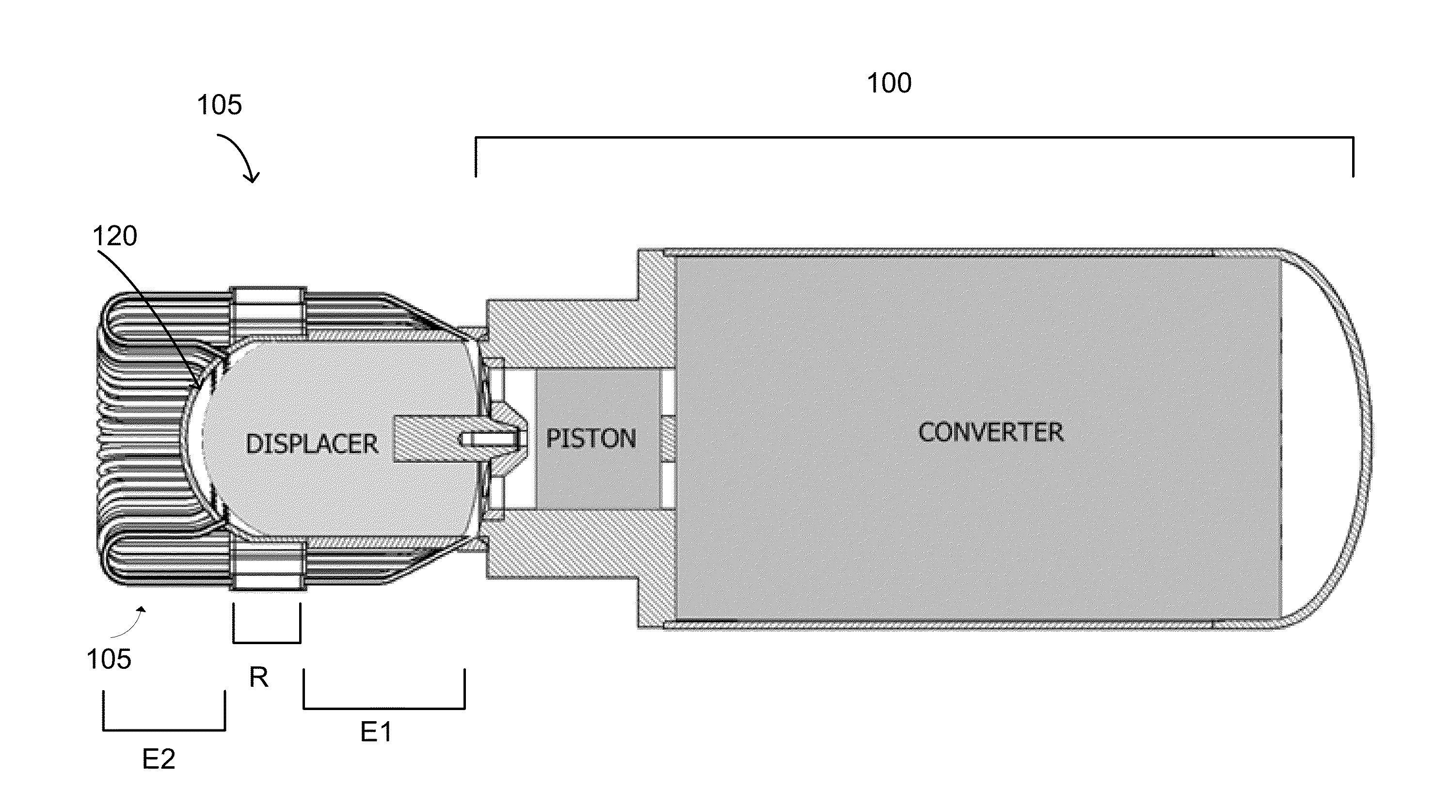
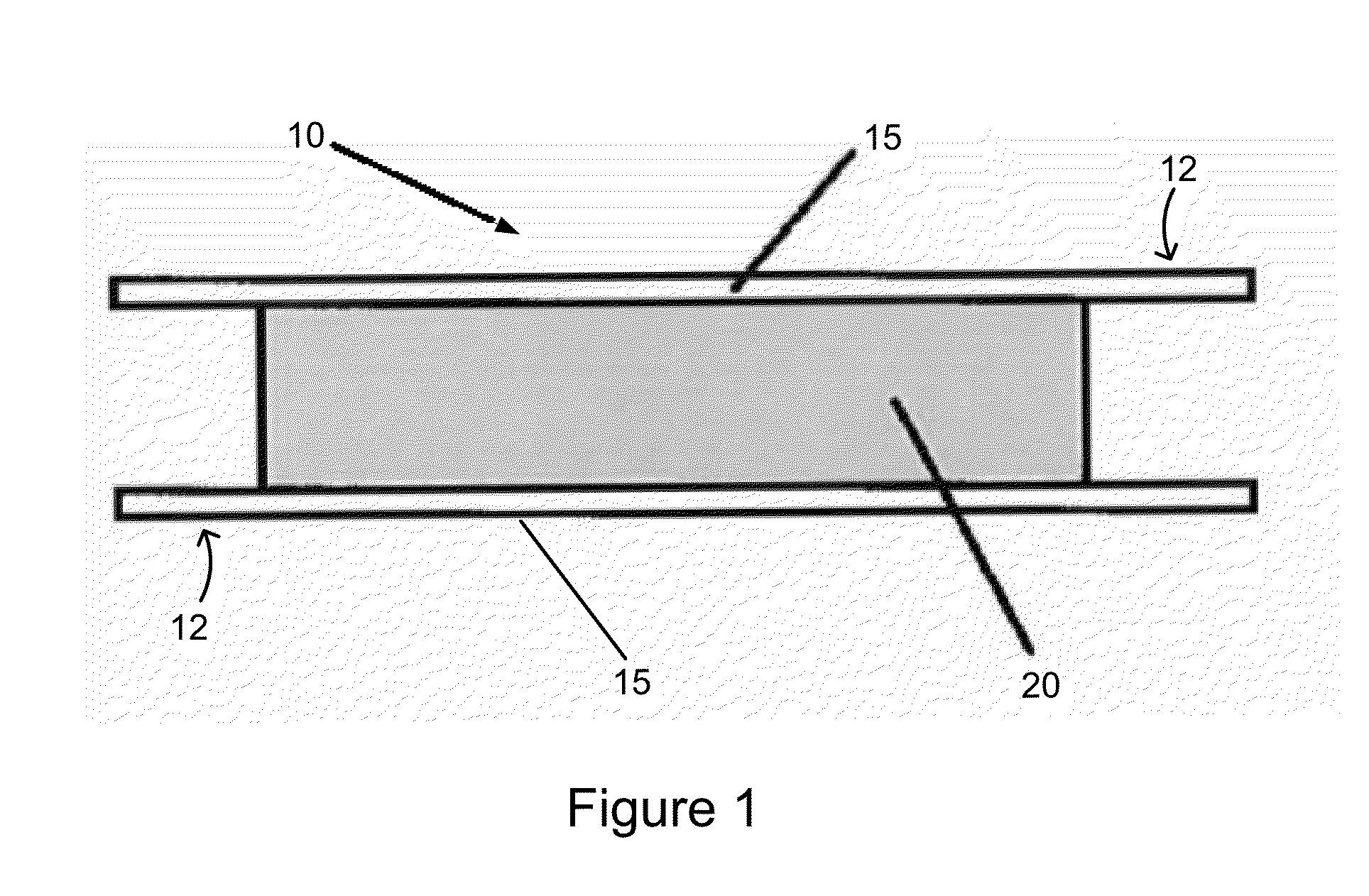
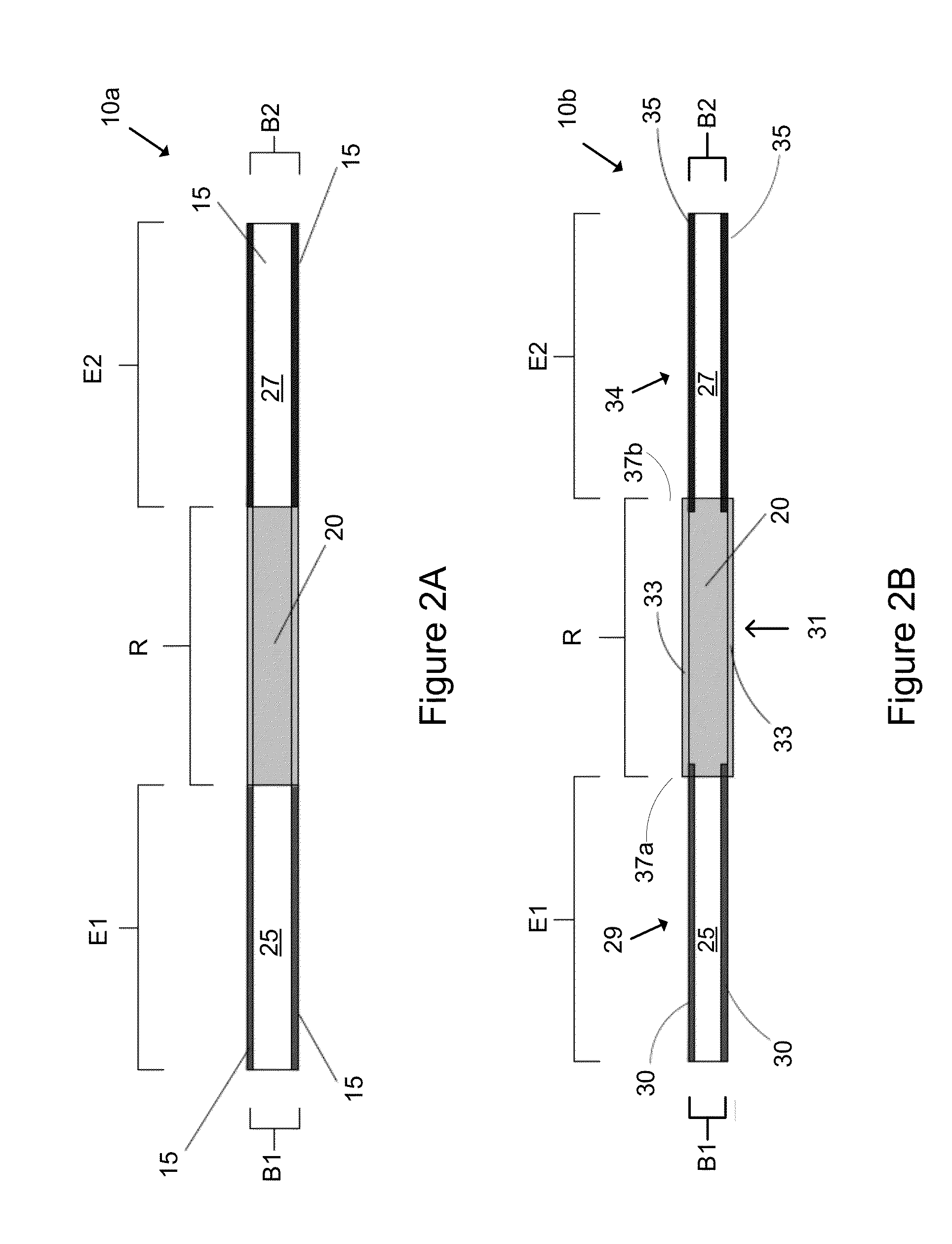
[0031]In one embodiment, the invention relates to a heat exchanger assembly such as a regenerator assembly for use with a thermodynamic cycle-based device such as a Stirling cycle machine. The heat exchanger assembly includes an acceptor heat exchanger, a regenerator heat exchanger, and a rejector heat exchanger and one or more assemblies. Typically, one heat exchanger assembly formed from one or more tubes is used. For example, a tube can be molded or formed to include a chamber or bulge having a larger diameter relative to the segments of the tube on either side of such a chamber or bulge. Alternatively, a first tube and a second tube can connect to a third tube or canister. A regenerator material is disposed in such a chamber or canister in one embodiment. Thus, one or more tubes or canisters can be connected in series.

[0032]Embodiments of the invention relate to a heat exchanger assembly that includes one or more tubes connected in series. As part of one embodiment, a regenerato...


PUM


Abstract

In one embodiment, the invention relates to a heat exchanger suitable for use with a thermodynamic cycle-based machine such as an engine, an energy conversion machine, a cooling machine or other suitable systems and machines. The heat exchanger can include one or more tubes arranged to form a heat exchanger. In one embodiment, a unitary tube is used. The heat exchanger can include a canister that includes a regenerator material. The canister can be in thermal communication with a working material and a containment vessel having a containment chamber in one embodiment.

Description

RELATED APPLICATIONS[0001]This application claims the benefit of U.S. Provisional Patent Application No. 61 / 599,232 filed Feb. 15, 2012, the entire disclosure of which is incorporated herein by reference.BACKGROUND[0002]Thermodynamic cycle-based machines such as Stirling engines and other devices often use a containment vessel having a containment chamber and heat exchangers along with other components to help convert heat into mechanical motion and to use such mechanical motion to provide cooling or electricity. Conventional heat exchanger assemblies for use with thermodynamic cycle-based machines typically contain many parts that have demanding assembly requirements.[0003]Containment vessels and other components of thermodynamic cycle-based machines are often subjected to extreme temperature environments for extended periods of time. Therefore, exotic materials having properties suitable for use in extreme temperature environments have been used to form heat exchanger assemblies. ...

Claims


Application Information

Patent Timeline
IPC IPC(8): F28D17/04
CPCF28D17/04F28D17/02F02G1/057F02G2257/00
Inventor AUGENBLICK, JOHN EDWARDMCFADDEN, GREGORY DAVIDPETERSON, ALLEN ANDREWRINK, KARL KUNO
Owner QNERGY
Why Eureka
Try Eureka