
Container for collecting waste lubricant

a technology for collecting containers and lubricants, applied in the direction of lubricating pumps, engine components, machines/engines, etc., can solve the problems of lubricant escaping, prone to bleeding, and the inability to empty the collection container again or only with effor

Active Publication Date: 2013-08-15
PERMA TEC
View PDF2 Cites 8 Cited by
  • Summary
  • Abstract
  • Description
  • Claims
  • Application Information

AI Technical Summary

Benefits of technology

This patent describes a sealing arrangement for a lubricant collecting container in which a sealing surface is formed on the piston or cover and an elastomer seal is used to seal the container after it is filled with lubricant. This arrangement ensures that the container is tightly sealed and prevents any leakage between the outer edge of the piston and the container's housing. This allows for smooth movement of the piston and reduces friction while in use.

Problems solved by technology

The problem with the piston system is that if the collecting container is filled with lubricant and lubricant continues to flow, the lubricant can escape out of the collecting container past the piston.
This is in particular a problem when a piston has to be built so that it can be moved particularly easily, that is with the lowest pressure difference and thus with low seal pressing and the old lubricant due to thermal stress and pressure stress tends to bleed out, that is, to segregate oil portions.
The disadvantage of the system with the membrane is that, after being filled, the collecting container cannot be emptied again or can be emptied again only with effort.

Method used


Image

  • Container for collecting waste lubricant
  • Container for collecting waste lubricant

Examples


Embodiment Construction

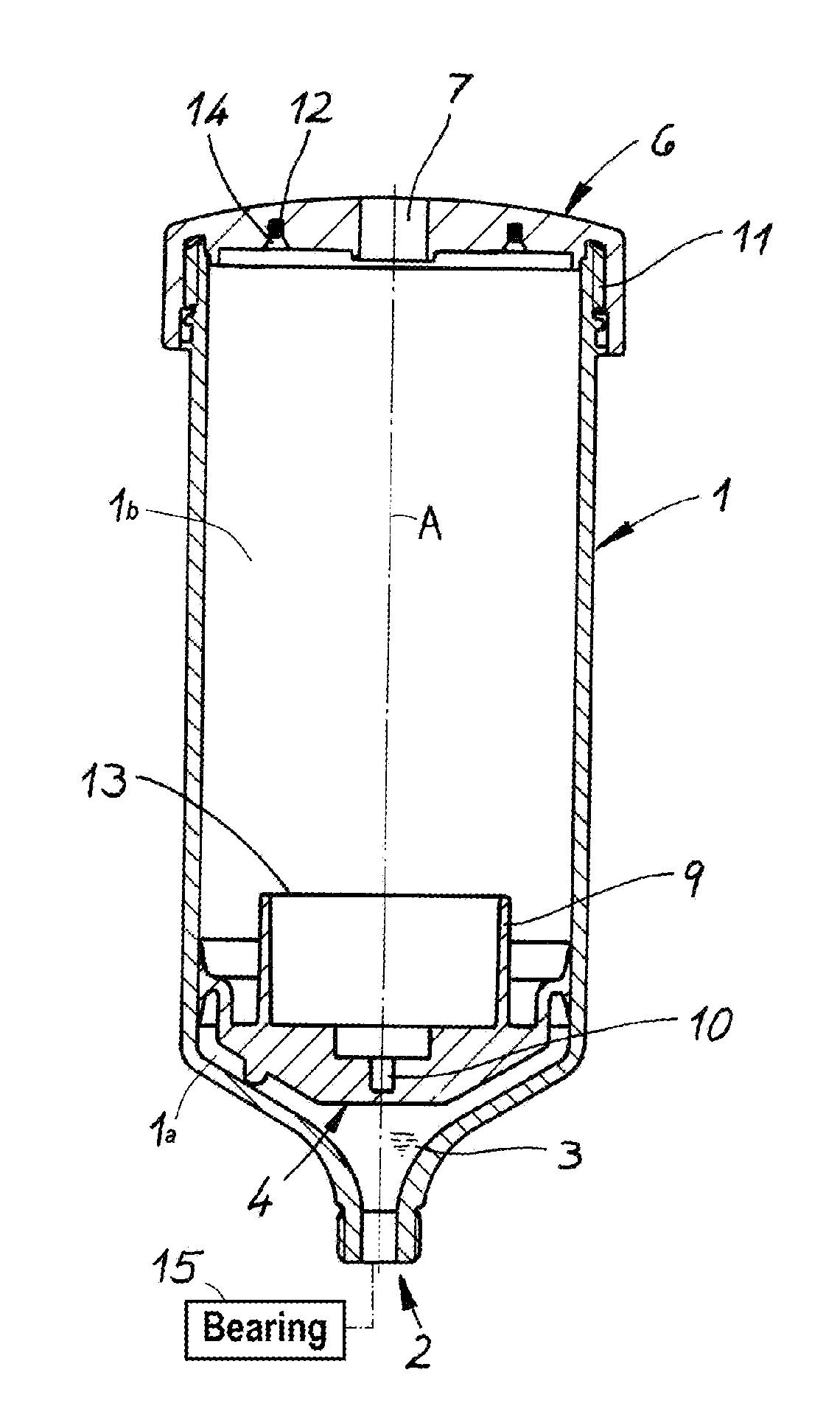
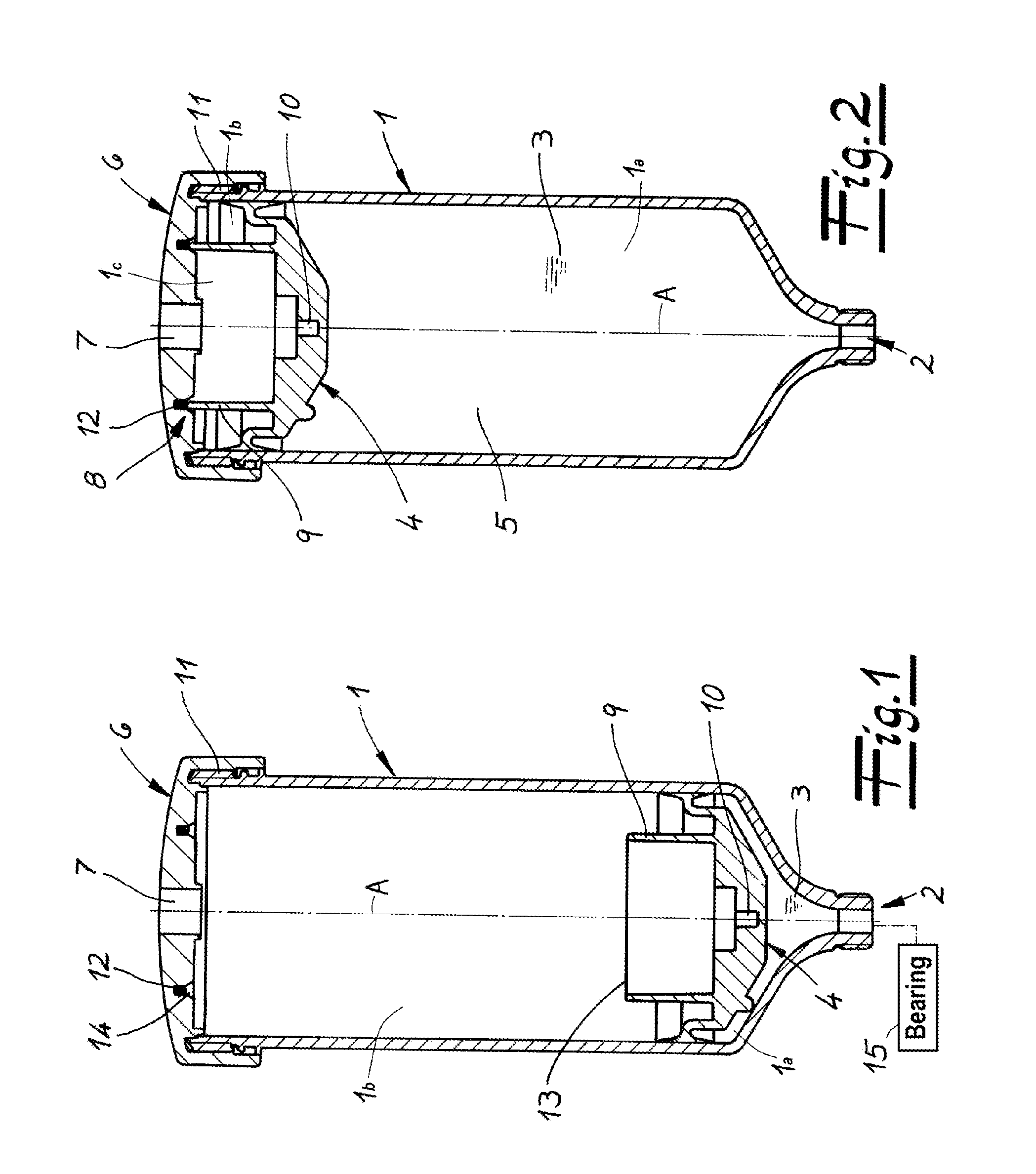
[0015]A container for collecting excess or waste liquid lubricant is formed as a cylindrical housing 1 centered on a normally upright axis A and having a inwardly tapered lower end forming an inlet opening 2 connected as shown schematically in FIG. 1 to a bearing 15. At its upper end the cylindrical housing 1 is closed by a cap 6 having a central throughgoing vent hole 7 and secured releasably in place by a screwthread 11.

[0016]A piston 4 of very light construction subdivides the interior 5 of the housing 1 into a lower waste compartment 1a normally filled with a mass or body 3 of the waste liquid lubricant from the bearing 15 and an upper compartment 1b that is normally open to the outside via the vent hole 7. The piston 4 has circular outer lips that engage radially outwardly against the cylindrical inner surface of the housing 1 and can slide freely between the lower position shown in FIG. 1 in which the compartment 1a is of minimal volume and the compartment 1b is of maximal vol...


PUM


Abstract

A container for collecting a liquid lubricant has a housing having one end formed with an inlet opening connectable to a source of the liquid lubricant and an opposite end formed with a vent hole, with a piston inside the housing subdividing the housing into a front lubricant compartment into which the inlet opening opens and a rear compartment into which the vent hole opens. The piston is shiftable between a front position close to the intake opening and a rear position close to the vent hole such that as the liquid lubricant fills the lubricant compartment the piston moves into the rear position. Formations on the piston and on the housing seal between the piston and the housing around the vent hole only when the piston is in the rear position.

Description

FIELD OF THE INVENTION[0001]The present invention relates to a lubricant-collecting container. More particularly this invention concerns such a container connected to a bearing to catch excess lubricant.BACKGROUND OF THE INVENTION[0002]Such a container as described in US patent publication 2012 / 0103465 has a cylindrical housing having one end formed with an intake opening connected to the source of liquid lubricant, typically a bearing connected to an automatic lubricant doser. In one embodiment a piston subdivides the container into a front compartment into which the intake opening opens and a back compartment that is open to the outside through the wide-open rear end of the container. The piston can thus be moved back as the compartment fills until it engages stops preventing further movement. In another embodiment the rear end of the container is covered with a cap having a vent hole and instead of a piston a bladder inside the container is compressed as the front compartment fil...

Claims


Application Information

Patent Timeline
Patent Type & Authority Applications(United States)
IPC IPC(8): F16N19/00
CPCF16N19/00F16N11/08
Inventor HILDENBRAND, THOMASEISENBACHER, EGON
Owner PERMA TEC
Learn More