Vibration damping mechanism

a technology of vibration damping and rotating shaft, which is applied in the direction of mechanical equipment, boring bars, manufacturing tools, etc., can solve the problems of reducing the strength of the tool holder, increasing the manufacture etc., and achieves the effects of stabilizing the rotation of the shaft section, enhancing the vibration energy absorption effect, and reducing the manufacturing cost of the vibration damping weigh

Active Publication Date: 2013-08-15
DAISHOWA SEIKI CO LTD
View PDF13 Cites 17 Cited by
  • Summary
  • Abstract
  • Description
  • Claims
  • Application Information

AI Technical Summary

Benefits of technology

[0018]With the above-described arrangement, since the displacement amount of the plurality of weight members away from the axis is restricted, returning displacement of the weight members toward the axis after their displacement away from the axis in association with vibration in the shaft section can be facilitated. So that, it becomes possible to stabilize the revolution of the shaft section and also to enhance the vibration energy absorption effect by the mutual sliding between the dividing faces.

Problems solved by technology

In accommodating a heavier weight within the hollow portion, if a weight having a large specific weight, but made of an expensive super-hard alloy or heavy metal is accommodated, this may invite increase in the manufacture cost of the vibration damping weight.
Also, if a weight having a small specific weight, but made of an inexpensive metal is accommodated, this may invite enlargement of the hollow portion, which leads in turn to reduction in the strength of the tool holder.

Method used


Image

  • Vibration damping mechanism
  • Vibration damping mechanism
  • Vibration damping mechanism

Examples


Embodiment Construction

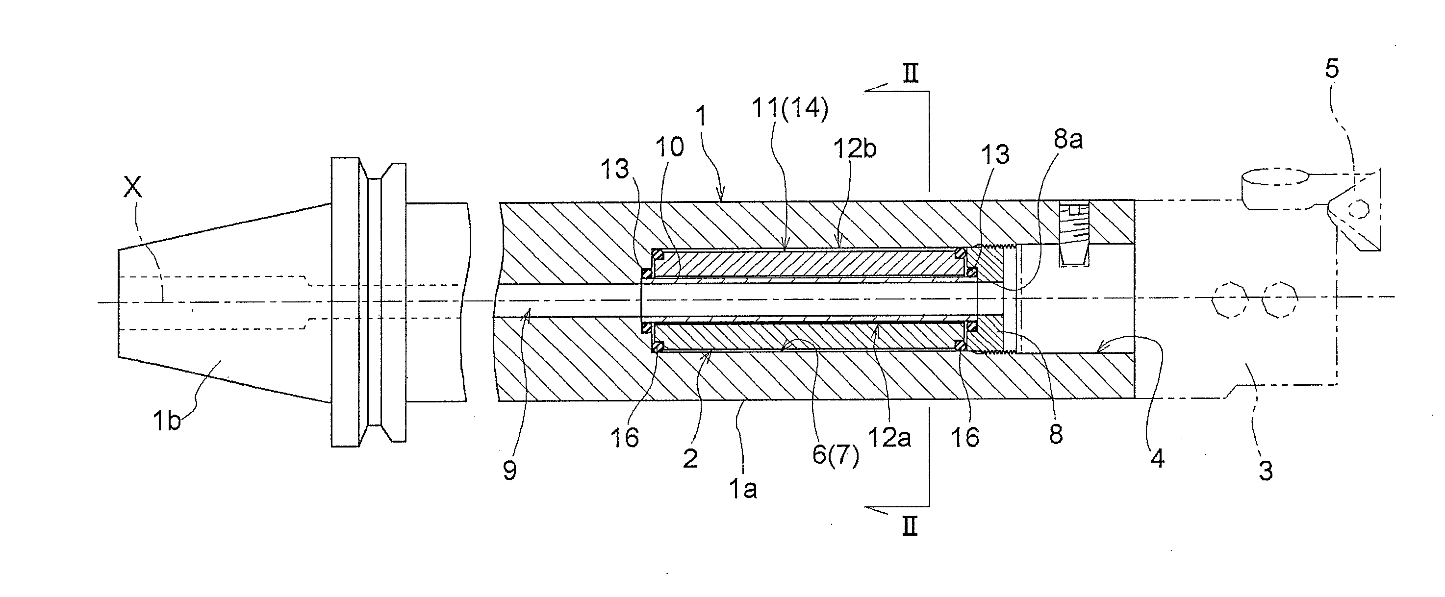
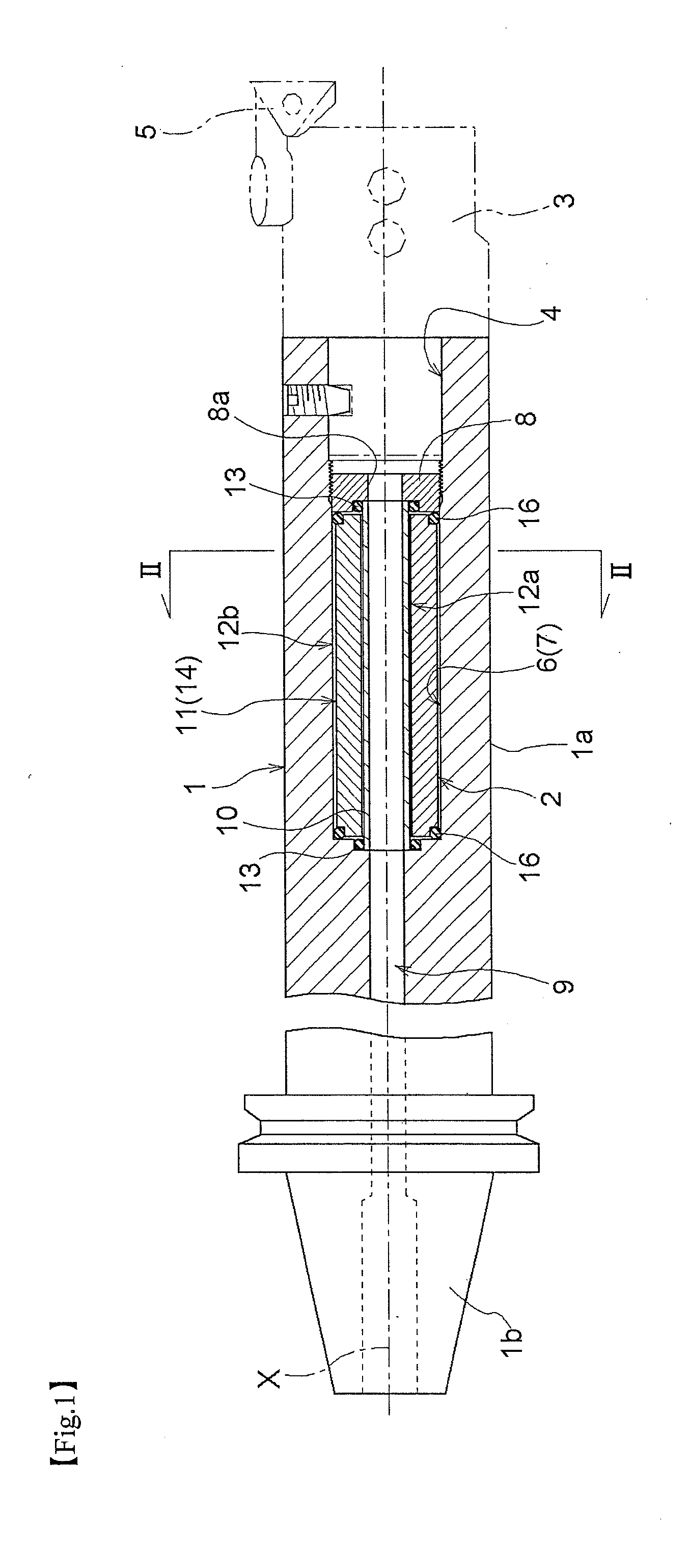
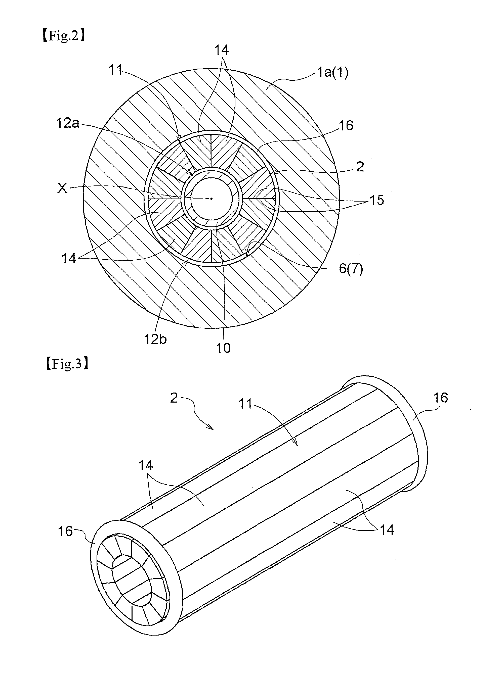
[0044]1. In the vibration damping mechanism according to the present invention, the weight members equidistantly divided from each other along the circumferential direction about the axis of the hollow portion may be further divided in the direction of the axis of the hollow portion also.

[0045]In this case, in association with chattering vibration of the shaft section, the dividing faces of the weight members adjacent each other in the direction along the axis of the hollow portion may be caused to slide against each other, so that the vibration energy can be absorbed as friction energy or impact energy between the dividing faces.

[0046]Further, if an annular elastic member is interposed between the outer circumferential face of each weight member and the inner circumferential face of the hollow portion, each weight member can be urged to move toward the axis of the hollow portion, whereby the inertial moment of the shaft section can be reduced, thus allowing smooth revolution of the...


PUM

PropertyMeasurementUnit
vibration dampingaaaaaaaaaa
weightaaaaaaaaaa
vibration energyaaaaaaaaaa

Abstract

A vibration damping mechanism allows increase of an absorption amount of vibration energy, with less possibilities of increase in the manufacture cost of a vibration damping weight and of reduction in the strength of a shaft section. Within a cylindrical hollow portion formed inside the shaft section, there are accommodated a plurality of weight members divided from each other along the circumferential direction about the axis of the hollow portion. An urging member is provided for urging the weight members toward the axis such that dividing faces of adjacent weight members are brought into surface contact with each other.

Description

TECHNICAL FIELD[0001]The present invention relates to a vibration damping mechanism wherein a vibration damping weight is accommodated within a cylindrical hollow portion formed inside a shaft section of a tool holder or the like coaxially with the axis of the hollow portion.BACKGROUND ART[0002]For a cutting work of metal, a tool holder having a cutter blade affixed to its leading end is attached to a machine tool in a cantilevered manner. Hence, the problem of deterioration in the working accuracy may occur if there occurs a so-called “chattering vibration” in the tool holder in the course of a cutting work for cutting metal which is effected by driven revolution of the tool holder.[0003]The above-described vibration damping mechanism is configured to cause the vibration damping weight accommodated in the hollow portion to be vibrated in such a manner to offset chattering vibration and also to absorb the energy of the chattering vibration if or when such chattering vibration occurs...

Claims


Application Information

Patent Timeline
Patent Type & Authority Applications(United States)
IPC IPC(8): F16F7/08
CPCB23B27/002B23B27/007F16F15/1435B23B29/022F16F2222/04F16F7/08F16F15/322Y10T408/76Y10T409/304312Y10T409/304424Y10T409/309408Y10T409/30952B23B27/00B23B29/02B23C9/00B23Q11/00F16F15/02
Inventor OGATA, TATSUYA
Owner DAISHOWA SEIKI CO LTD
Why Eureka
Try Eureka