Fuel injection valve supporting structure

Active Publication Date: 2013-08-29
HITACHI ASTEMO LTD
View PDF30 Cites 9 Cited by
  • Summary
  • Abstract
  • Description
  • Claims
  • Application Information

AI Technical Summary

Benefits of technology

[0006]The present invention has been made with the foregoing situation taken into consideration, and an object thereof is to provide the f

Problems solved by technology

The turn changes the direction in which fuel is injected from a nozzle portion of the f

Method used


Image

  • Fuel injection valve supporting structure
  • Fuel injection valve supporting structure
  • Fuel injection valve supporting structure

Examples


Embodiment Construction

[0022]An embodiment of the present invention will be described below based on the attached drawings.

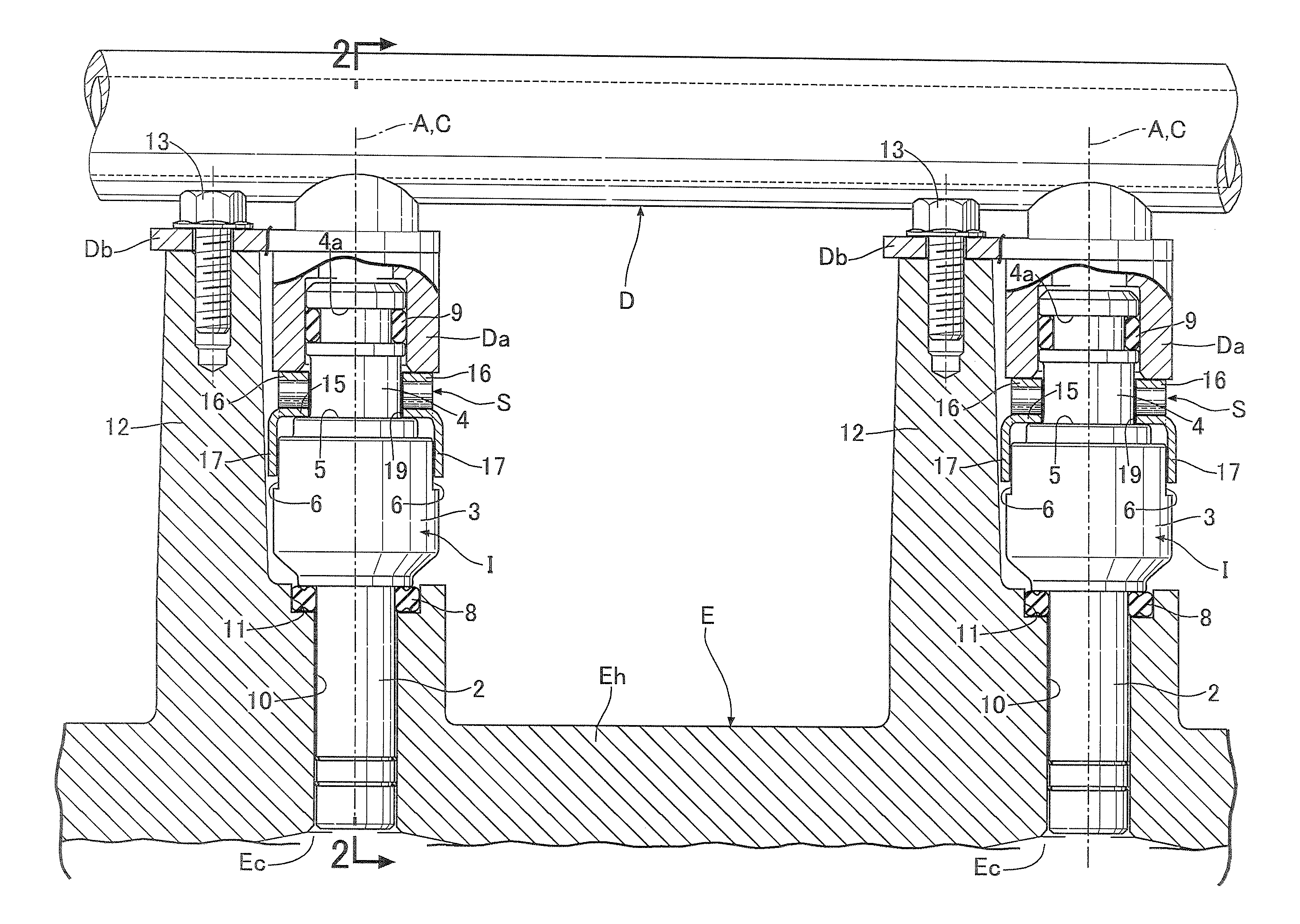
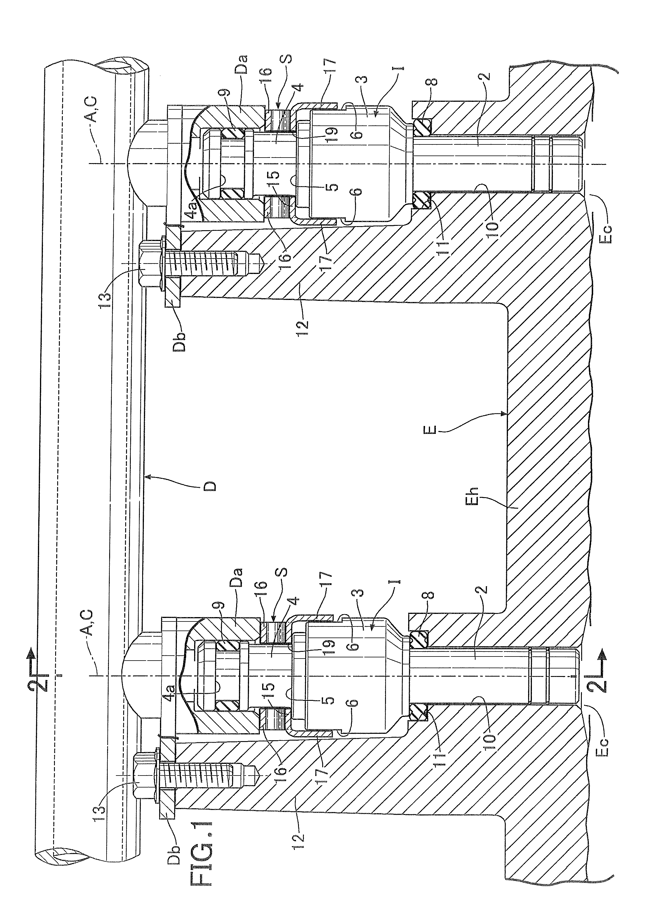
[0023]As shown in FIG. 1 and FIG. 2, first of all, multiple fuel injection valves I capable of injecting fuel to combustion chambers Ec of multiple cylinders and a fuel distribution pipe D configured to distribute the fuel to the fuel injection valves I are attached to a cylinder head Eh of a multi-cylinder engine E. In addition, a supporting member S is interposed between each fuel injection valve I and the fuel distribution pipe D in order that the fuel injection valve I should not be displaced in its axial direction or about a center axis A. Detailed descriptions of the structure will be provided hereinbelow.

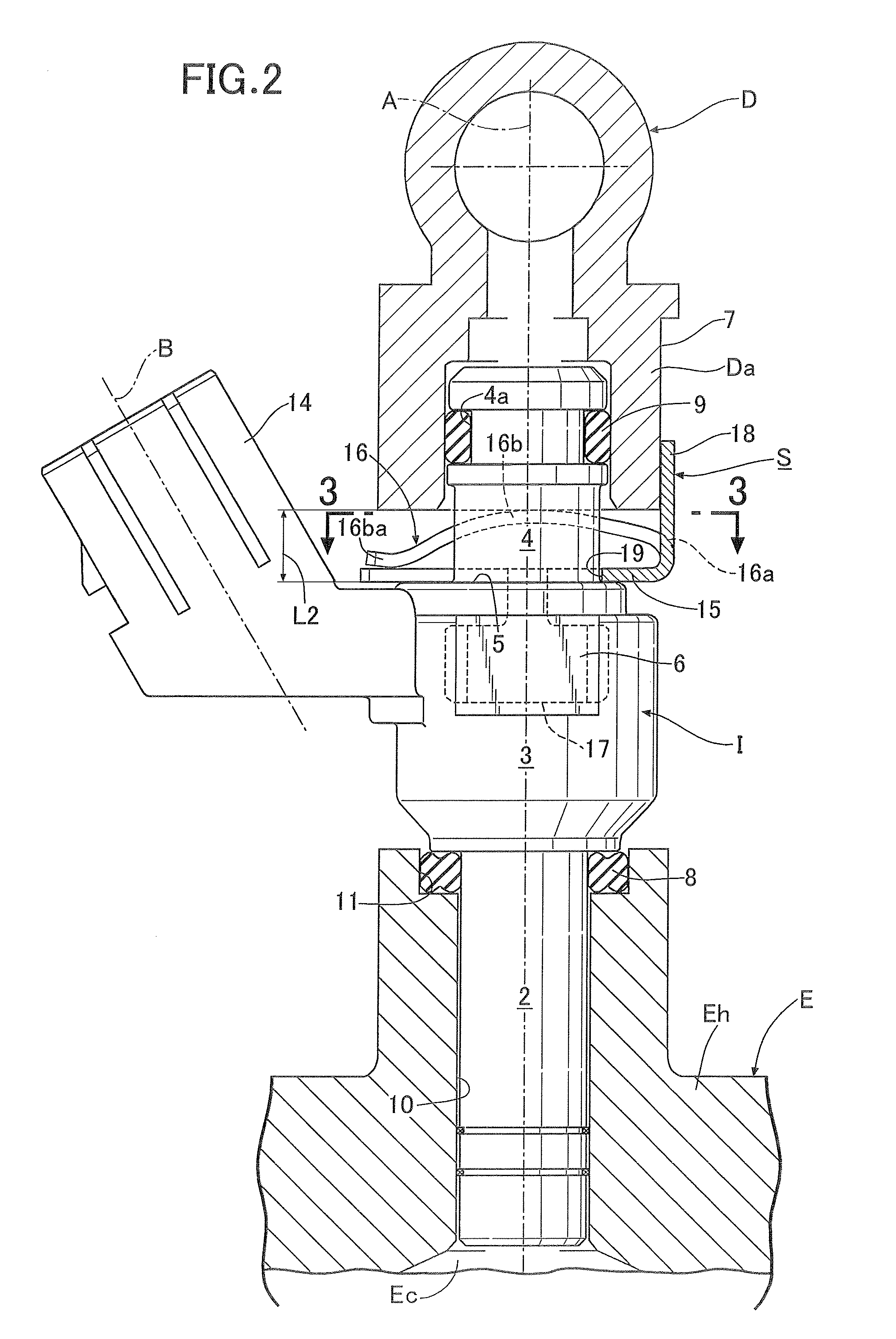
[0024]Each fuel injection valve I is formed from a cylindrical nozzle portion 2, an electromagnetic coil portion 3 and a fuel introduction portion 4 which are coaxially continuous with one another from a front end toward a rear end of the fuel injection valve I. When electricit...


PUM


Abstract

In a fuel injection valve supporting structure, a first contact surface being orthogonal to a center axis of a fuel injection valve and opposed to a fuel supply cap and paired second contact surfaces opposed to each other with a plane, including the center axis and a center line of a coupler, in between are formed in an intermediate portion of the fuel injection valve, and a supporting member includes: a base plate set on the first contact surface; an elastic piece extending from the base plate to elastically come into pressure contact with the fuel supply cap and bias the fuel injection valve toward an injection valve attachment hole by its reaction force; and paired turn stopper pieces each extending from the base plate to abut against the second contact surface and restrict a turn of the fuel injection valve about the center axis.

Description

BACKGROUND OF THE INVENTION[0001]1. Field of the Invention[0002]The present invention relates to an improvement of a fuel injection valve supporting structure in which: a nozzle portion at a front end portion of a fuel injection valve projectingly provided with a power supply coupler on one side surface of the fuel injection valve is fitted in an injection valve attachment hole of an engine; a fuel supply cap of a fuel distribution pipe supported by the engine is fitted on a fuel introduction portion at a rear end portion of the fuel injection valve; a supporting member for biasing the fuel injection valve toward the injection valve attachment hole is interposed between the fuel injection valve and the fuel supply cap.[0003]2. Description of the Related Art[0004]Such a fuel injection valve supporting structure is already known, as disclosed in Japanese Patent Application Laid-open No. 2004-245168.[0005]With regard to such a conventional fuel injection valve supporting structure, a U...

Claims


Application Information

Patent Timeline
IPC IPC(8): F02M69/04
CPCF02M69/04F02M55/025F02M61/14F02M2200/857F02M2200/852F02M2200/853F02M2200/856F02M2200/26
Inventor NAKAMURA, NAKAYAWAKAMATSU, MANABUMACHIDA, KEISUKEARIOKA, AKIRA
Owner HITACHI ASTEMO LTD
Why Eureka
Try Eureka