
Packaging apparatus and method for compressor

a compressor and packaging technology, applied in the field of packaging compressor accessories and methods, can solve the problems of damage to the welding portion between the compressor body and the end cap, difficulty in packaging the compressor under the state that the compressor stands stably,

Active Publication Date: 2008-12-02
SANYO ELECTRIC CO LTD +1
View PDF12 Cites 3 Cited by
  • Summary
  • Abstract
  • Description
  • Claims
  • Application Information

AI Technical Summary

Benefits of technology

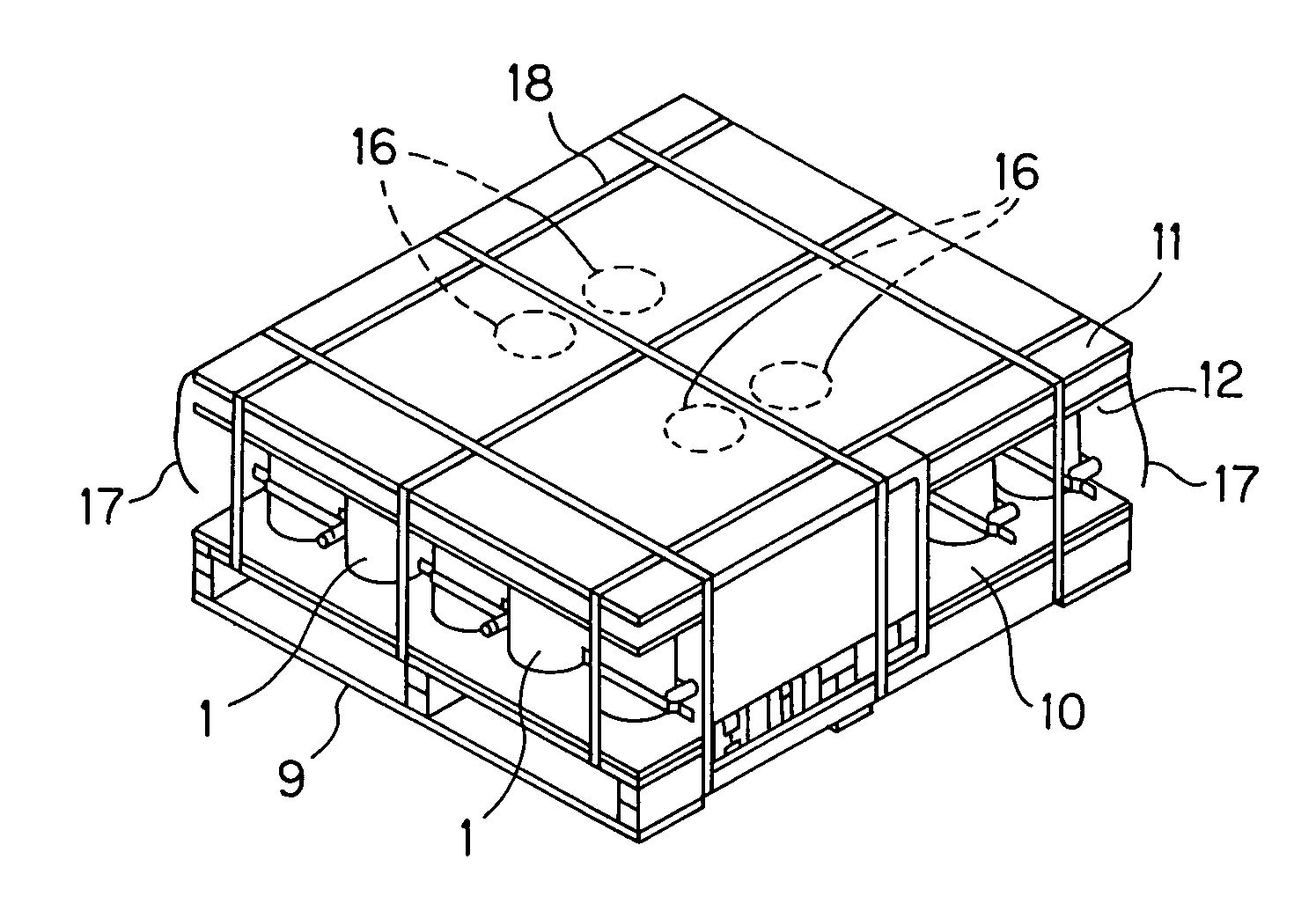
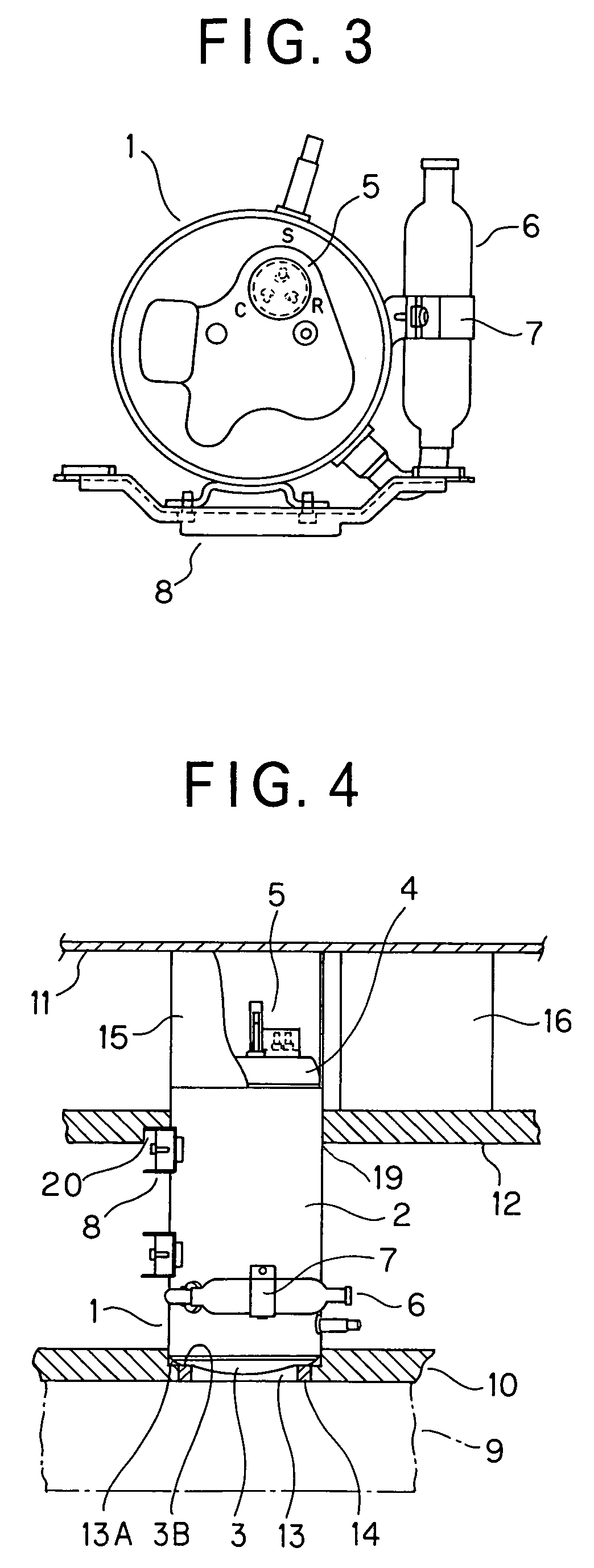
The present invention provides a compressor packaging apparatus and method that can stably raise compressors without damaging them due to vertical vibration or wiggling. The apparatus includes a lower plate and an upper plate between which the compressors are sandwiched and fixed using first paper pipes fitted in stepped fitting portions of the lower plate. The compressors are also supported by second paper pipes covered on the end caps of the compressors, and third papers are disposed between the upper plate and an intermediate plate to restrict turning of the compressors. The apparatus and method can pack compressors with dish-shaped end caps, and prevent damage to the compressors during transportation.

Problems solved by technology

However, with respect to a compressor having no fixing board at the end cap and a horizontal set type compressor in which a fixing board is provided to the peripheral side surface of the compressor body, it is difficult to package the compressor under the state that the compressor stands stably.
However, with respect to the compressor having no fixing board at the end cap and the horizontal set type compressor in which a fixing board is provided to the peripheral side surface of the compressor body, these compressors are unstable when they are transported, and there is a risk that the welded portion between the compressor body and the end cap, etc. are damaged by vertical vibration or waggling.

Method used


Image

  • Packaging apparatus and method for compressor
  • Packaging apparatus and method for compressor
  • Packaging apparatus and method for compressor

Examples


Embodiment Construction

[0036]Preferred embodiments according to the present invention will be described hereunder with reference to the accompanying drawings.

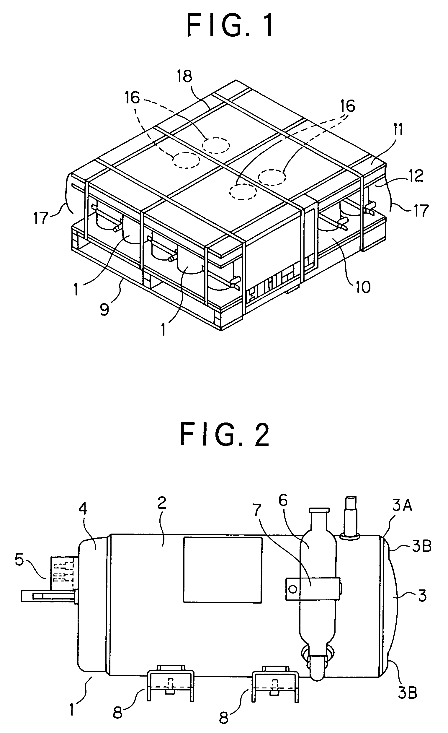
[0037]A compressor 1 is designed so that dish-shaped end caps 3 and 4 are fixed to both the ends of a cylindrical compressor body 2 by welding as shown in FIGS. 2 and 3. An annular flat portion 3B is provided in the vicinity of the peripheral edge portion 3A serving as a welding portion of the end cap 3. A connection terminal 5 is provided to the end cap 4 so as to project from the end cap 4. An accumulator 6 is connected to the compressor body 2, and it is held on the compressor body 2 by a fixing band 7. Two fixing boards 8 are provided to the lower portion on the peripheral side surface of the compressor body 2. Accordingly, the compressor 1 is designed as a horizontal set type compressor that is fixed to a machine house of an air conditioner or the like.

[0038]Twenty five compressors 1 each of which has the above construction are packaged as one s...


PUM

PropertyMeasurementUnit
shapeaaaaaaaaaa
sizeaaaaaaaaaa
timeaaaaaaaaaa

Abstract

A compressor packaging apparatus for fixing plural compressors each of which has dish-shaped end caps at both the upper and lower end portions of a cylindrical compressor body, including an upper plate and a lower plate between which the compressors are sandwiched and fixed, the lower plate being equipped with a plurality of stepped fitting portions in which the lower end caps of the compressors are fitted, and first paper pipes fitted to the stepped fitting portions. Furthermore, an intermediate plate having plural insertion holes in which the compressor bodies are inserted is provided, and second paper pipes fitted to the end caps at the upper portions of the compressors and third paper pipes may be provided between the upper plate and the intermediate plate.

Description

BACKGROUND OF THE INVENTION[0001]1. Field of the Invention[0002]The present invention relates to apparatus and method for packaging compressors when plural compressors are transported, stored, etc.[0003]2. Description of the Related Art[0004]A compressor is generally designed so that dish-like end caps are provided to both the end portions of a cylindrical compressor body, and a connection terminal is provided to one end cap so as to project from the end cap concerned while a fixing board is provided to the other end cap as disclosed in JP-A-6-255674. In the case of a packaging apparatus for the compressor disclosed in JP-A-6-255674, the fixing board is provided to the end cap at the lower portion of the compressor, and thus the compressor can be pinched between a lower plate and an upper plate under a stable state by directly fixing the fixing board to the lower plate or engagedly fitting the fixing board to the lower plate.[0005]However, with respect to a compressor having no fixi...

Claims


Application Information

Patent Timeline
Patent Type & Authority Patents(United States)
IPC IPC(8): B65D85/68
CPCB65D19/44B65D85/68B65D81/113B65D71/70F21V3/10F21V3/02
Inventor HARA, MASAYUKISAKANIWA, MASAZUMIKANAYAMA, TAKAO
Owner SANYO ELECTRIC CO LTD
Learn More