Apparatus for treating eye tissue with laser pulses

a technology of eye tissue and laser pulse, which is applied in the field of ophthalmological equipment for treating eye tissue with laser pulse, can solve the problems that the accuracy of corneal cuts cannot be sufficient, and achieve the effect of expanding flexibly and easily the treatment area of the ophthalmological equipmen

Active Publication Date: 2013-08-29
ZIEMER OPHTHALMIC SYST
View PDF9 Cites 23 Cited by
  • Summary
  • Abstract
  • Description
  • Claims
  • Application Information

AI Technical Summary

Benefits of technology

[0018]In a further embodiment, the ophthalmological patient interface device further comprises a mirror arranged at an angle with respect to a projection axis of the optical projection system in an area between the coupling part and the contact part, such that the laser beam projected by the optical projection system is deflected by the mirror when the ophthalmological patient interface device is attached mechanically to the optical projection system. In this case, the device identifier indicates a type of the ophthalmological patient interface device comprising a mirror, a position of the mirror, and / or an angular arrangement of the mirror. The mirror of the ophthalmological patient interface makes it possible to extend flexibly and easily the treatment area of the ophthalmological apparatus or add new treatment procedures, respectively, which would otherwise not be possible with conventional configurations.

Problems solved by technology

On the other hand, the mechanical deformation of the cornea caused by placing the contact body on the cornea may produce undesirable side effects such as corneal folds that disturb the focus behind the posterior surface of the cornea.
On the other hand, the liquid interface of US 2010 / 0274228 does not place the cornea in a sufficiently defined position with respect to a projection lens so that accurate corneal cuts can only be made by using complex imaging feedback systems and real-time position control during operation, while some corneal cuts cannot be performed with sufficient accuracy at all.

Method used


Image

  • Apparatus for treating eye tissue with laser pulses
  • Apparatus for treating eye tissue with laser pulses
  • Apparatus for treating eye tissue with laser pulses

Examples


Embodiment Construction

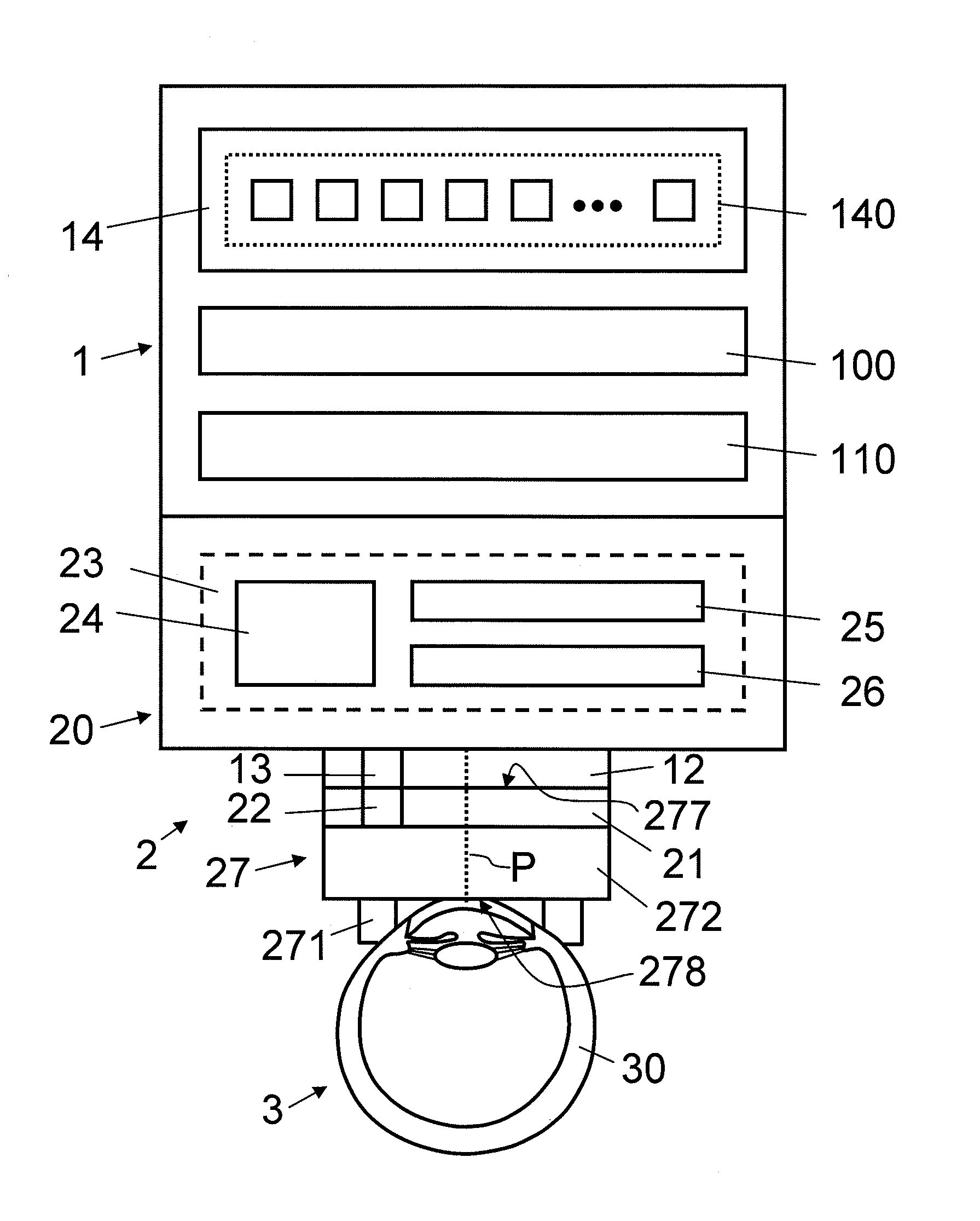
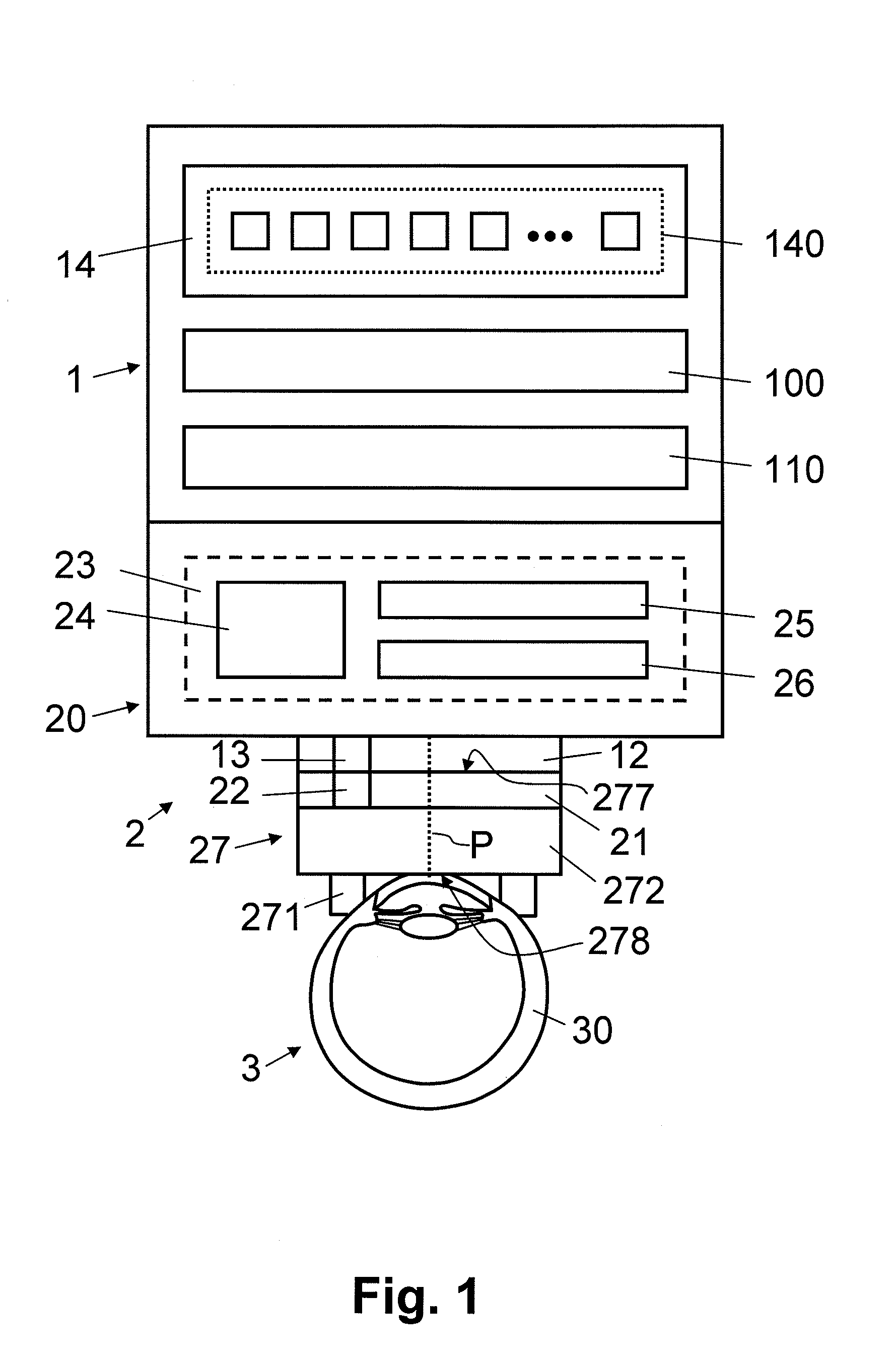
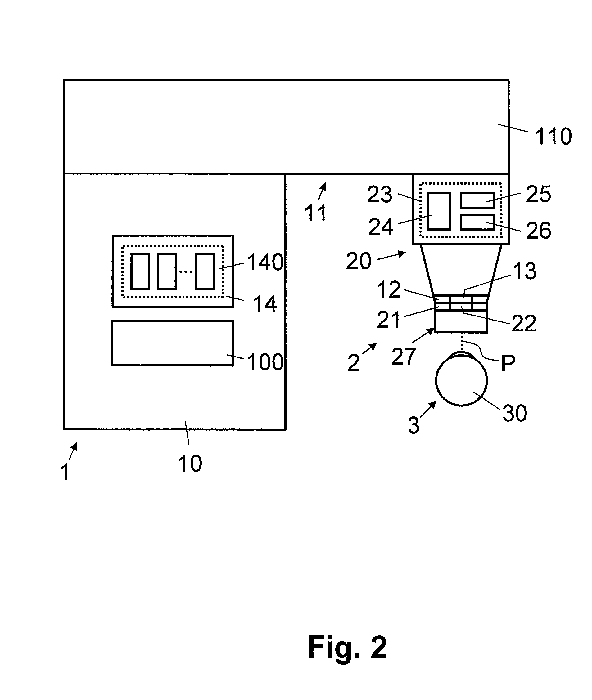
[0029]In FIGS. 1, 2, 3, 4, 5 and 8, reference numeral 1 refers to an ophthalmological apparatus for treating eye tissue 30 with laser pulses P. As is illustrated schematically in FIGS. 1, 2, 3, 4, 5 and 8, the ophthalmological apparatus 1 comprises a laser source 100 and a control module 14. Depending on the embodiment, the laser source 100 and the control module 14 are arranged in a base station 10, as shown in FIGS. 2, 3, 4, for example. The laser source 100 is configured to generate a pulsed laser beam L, L′, L*, L1, L2, L3 (see FIG. 5, 8 or 9), e.g. a beam of femtosecond laser pulses P. In an embodiment, the laser source 100 is configured to generate a pulsed laser beam L, L′, L*, L1, L2, L3 with a selectable wavelength in the IR-A-infrared range, the IR-B-infrared range, and / or the UVA-ultra violet range. Depending on the embodiment, the laser source 100 includes one or more lasers and / or a frequency modulation module for generating the laser beam L, L′, L*, L1, L2, L3 with alt...


PUM


Abstract

An ophthalmological apparatus (1) for treating eye tissue (3) with laser pulses (P) comprises a laser source (100, an optical projection system (20) for projecting the laser pulses (P) onto the eye tissue (30), and a coupling part (12) for attaching mechanically to the optical projection system (20) an ophthalmological patient interface device (27) which is in contact with the eye (3) during treatment. The ophthalmological apparatus (1) further comprises a detector (13) for determining a device identifier (22) associated with the ophthalmological patient interface device (27), and a control module (14) for controlling the ophthalmological apparatus (1) using the device identifier (22). The detector makes it possible to use and detect different types of ophthalmological patient interface devices (27) and to adapt automatically the treatment of the eye tissue (30), depending on the ophthalmological patient interface device (27) that is presently attached to the ophthalmological apparatus (1).

Description

[0001]The present application claims benefit of and priority to U.S. Provisional Patent Application Ser. No. 61 / 604,149 filed Feb. 28, 2012 entitled Apparatus for Treating Eye Tissue with Laser Pulses, the entire content of which is hereby incorporated by reference herein.BACKGROUND[0002]1. Field of the Disclosure[0003]The present invention relates to an ophthalmological apparatus for treating eye tissue with laser pulses and to an ophthalmological patient interface device. Specifically, the present invention relates to an ophthalmological apparatus comprising a laser source for generating the laser pulses, an optical projection system for projecting the laser pulses, and a coupling part for attaching mechanically to the optical projection system an ophthalmological patient interface device which is in contact with the eye during treatment, and to an ophthalmological patient interface device comprising a coupling part configured to attach mechanically the ophthalmological patient in...

Claims


Application Information

Patent Timeline
Patent Type & Authority Applications(United States)
IPC IPC(8): A61F9/009
CPCA61F9/00825A61F9/00831A61F9/00836A61F9/009A61F2009/00897A61F2009/0087A61F2009/00872A61F2009/00893A61F2009/00865F04C2270/041
Inventor RATHJEN, CHRISTIAN
Owner ZIEMER OPHTHALMIC SYST
Why Eureka
Try Eureka